Topic: Developers
Satellite Data Delivery for Any Logger: RockREMOTE Mini’s SMTP Server
From the Solutions Team
This article was written by Michael Mitrev, Solutions Architect in Ground Control’s pre-sales Solutions team. Michael has been closely involved in the development and testing of the RockREMOTE Mini and RockBLOCK RTU, with a particular focus on data logger integrations. Here, he shares practical implementation guidance, configuration examples and lessons learned from hands-on testing and customer deployments.
If your device can send an email, it can send data over Iridium. No custom protocol, no firmware changes, no serial AT commands. Just point it at the Mini.
Quick Links: NRG SymphoniePRO | Campbell Scientific Loggers | Axis Communications Cameras
RockREMOTE Mini SMTP Server
RockREMOTE Mini runs a local SMTP server on its Ethernet interface, accessible at 192.168.250.1 port 25 by default. Any device on the Mini’s local network can connect to it and send a standard SMTP message with a file attachment. That’s it, as far as your device is concerned. The Mini takes care of everything that happens next.
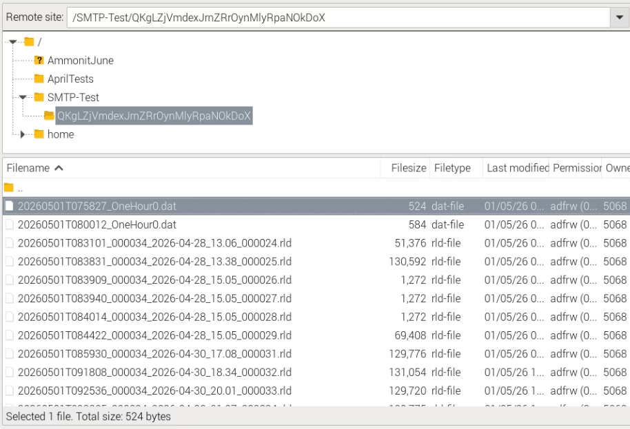
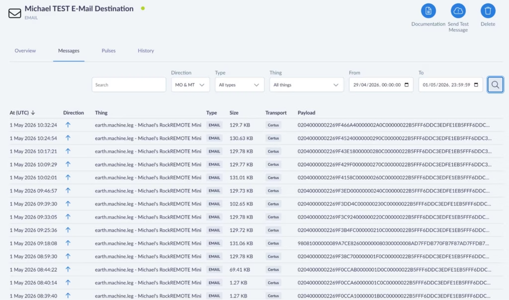
Example screenshot showing an FTP server destination with NRG RLD files and Campbell DAT filesInternally, the Mini compresses the attachment and transmits it as one or more IMT (Iridium Message Transport) messages over the Iridium Certus 100 network to Cloudloop Data. Cloudloop decompresses it and delivers it to your configured destination, which could be an inbox, a webhook, FTP server, an S3 bucket, or any other destination Cloudloop Data supports. Your device never needs to know any of this is happening.
A few key constraints worth knowing upfront:
- Max attachment size: 165 KB
- Recipients: one To field, up to two CC fields
- Authentication: none required (and none currently supported – leave username/password blank) with the exception of NRG Loggers
- Port: 25 only
The SMTP server must be enabled in the Mini’s user configuration file, and you need an Email Destination set up in Cloudloop Data with your Mini in the relevant device group (select Payload, Plaintext, and Assume Destination from Source).
What’s the Point?
Using SMTP isn’t really about sending Email. While it absolutely can be used to send email end-to-end, I don’t really see it as an email feature. I see it as a universal file transport mechanism.
If you’ve worked with SBD or IMT products before, you’ll know that you’re normally just sending the raw data. If that data happens to be a file, it’s then up to your individual applications on both the sending and receiving end to preserve or reconstruct the filename, extension and format, as well as implement whatever message handling, retries and timeouts needed to get it there in the first place.
With the Mini’s SMTP server, we’ve already solved that. Your device simply sends what it thinks is a normal email with an attachment, and at the other end you receive the original file with its filename, extension and format intact.
It’s essentially a one time setup on your side that results in complete files arriving at their destination without having to write any file reconstruction logic – we’ve taken care of that and the internal message handling process for an almost-guaranteed file receipt.
Why IMT?
When your attachment lands at the Mini’s SMTP server, it doesn’t go out over IP; it goes out over IMT. That distinction matters for running costs.
IMT is Iridium’s message-based transport protocol. Unlike IP, it carries no per-packet header overhead, and its minimum billable unit is 25 bytes (1 byte increments thereafter) rather than IP’s 1 KB (100 byte increments thereafter). For periodic data delivery – a file every hour, or once a day – this makes a meaningful difference to your airtime bill over a long campaign. The Mini also compresses attachments before sending, which reduces the byte count further.
For most monitoring deployments, SMTP over IMT is the right choice for scheduled data delivery: low cost, reliable, and completely hands off once configured.
IP and IMT Simultaneously
The Mini runs IP and IMT at the same time. This is worth emphasising, because it means your scheduled data delivery over IMT doesn’t stop you from also using the IP link for other purposes.
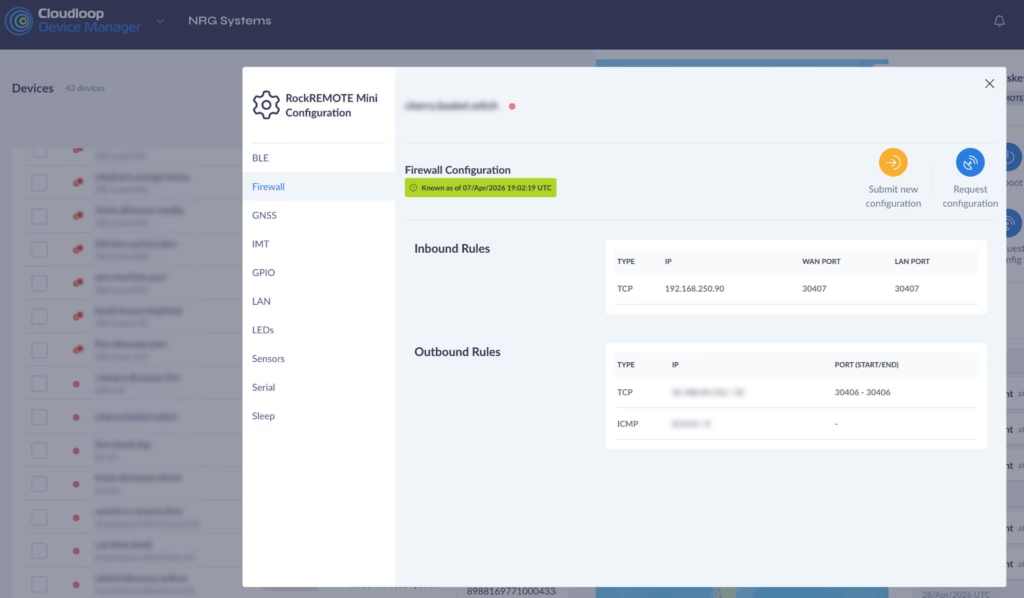
The Mini’s public IP (assigned and managed by Ground Control) can be used with port forwarding rules to provide direct access to any device on the Mini’s local network – your logger, your sensor hub, a web interface. These rules are configured either in the Mini’s user configuration file, pushed over the air via Cloudloop Device Manager, or set up via the RockCONNECT IoT BLE app.
Cloudloop NOC also offers whitelisting of public IP addresses that are allowed to reach your Public IP, it’s a block-all by default.
A typical inbound rule – forwarding connections on a WAN port through to a specific device (NRG Logger in this case) on the LAN:
And if the logger needs to initiate outbound connections to a specific server (NRG’s in this case):
The Mini’s IP link runs at 22 Kbps Transmit and 88 Kbps Receive – more than enough for remote access, configuration changes, and live data viewing. IMT handles the low cost scheduled delivery; IP handles everything interactive. You get both, from the same device, on the same Iridium link and with five or more devices you can benefit from a shared data pool.
NRG SymphoniePRO + iPackACCESS
NRG Systems’ SymphoniePRO is one of the most widely deployed meteorological data loggers in the wind energy industry, used globally for resource assessment and power performance campaigns. It has had SMTP data delivery built in from the start, making it a natural fit for the Mini’s SMTP server.

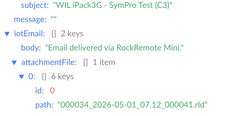
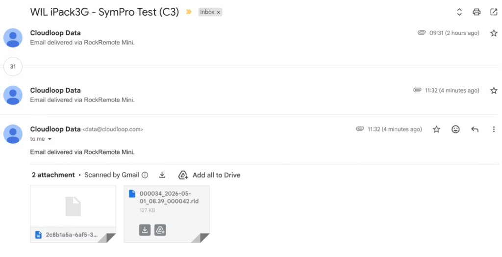
The iPackACCESS is the communications and power module that attaches to the back of the SymphoniePRO. It provides the logger with an Ethernet interface and handles all outbound communications: SMTP delivery of .RLD data files on a scheduled basis, and MetLink connections for interactive remote access via the SymphoniePRO Desktop Application.
Integrating with the RockREMOTE Mini is straightforward:
- Connect the iPackACCESS’s Ethernet port to the Mini’s LAN
- In SymphoniePRO Desktop Application, assign the iPackACCESS a static IP in the Mini’s subnet (e.g. 192.168.250.90)
- Set the SMTP server to 192.168.250.1, port 25
- The logger delivers .RLD files to Cloudloop Data on its configured schedule, which can then be accessed via NRG Cloud or pulled directly into SymphoniePRO Desktop Application as normal.
For MetLink remote access – live data, configuration changes, manual data pulls – configure an inbound port forwarding rule in the Mini pointing to the iPackACCESS’s LAN IP. If using logger-initiated MetLink, add a corresponding outbound rule allowing the logger to reach your server. Ground Control assigns a static public IP to your Mini; SymphoniePRO Desktop Application connects to that IP on the forwarded port and communicates with the iPackACCESS exactly as if it were going over terrestrial WAN networks.
NRG Systems are trusted partners of Ground Control. They worked closely with us during development of the Mini’s SMTP functionality to ensure it integrates correctly with the SymphoniePRO and iPackACCESS system, so if you’re an NRG customer looking to add Iridium satellite telemetry, they’re fully across this solution and can handle the setup end to end. We’d strongly recommend reaching out to them directly!
Campbell Scientific Loggers
Campbell loggers – CR1000, CR6, CR300, CR800, CR1000X and others – have had the EmailSend function in CRBasic for many years. It can stream data table records as file attachments on a scheduled basis, over SMTP.

Getting a Campbell logger talking to the Mini requires minimal changes to an existing program: set the SMTP server address to 192.168.250.1:25, and leave the username and password fields as empty strings. Your data tables, scan intervals, and field processing don’t need to change at all – just add the SMTP function and the only prerequisite is to have the logger connected via Ethernet to the RockREMOTE Mini and a static or DHCP IP set in the same subnet.
EmailSend with FileOption 8 produces TOA5-format output: headers, timestamps, and record numbers in the standard Campbell ASCII format, compatible with LoggerNet, PC400, and most downstream tools. The time-window arguments let you stream the last hour of records, the last day, or all records since the last reboot.
For remote access, the same port forwarding approach applies. IP at 88 Kbps Receive and 22 Kbps Transmit is more than comfortable for LoggerNet connections – editing programs, pushing updates, pulling live data or on demand table records.
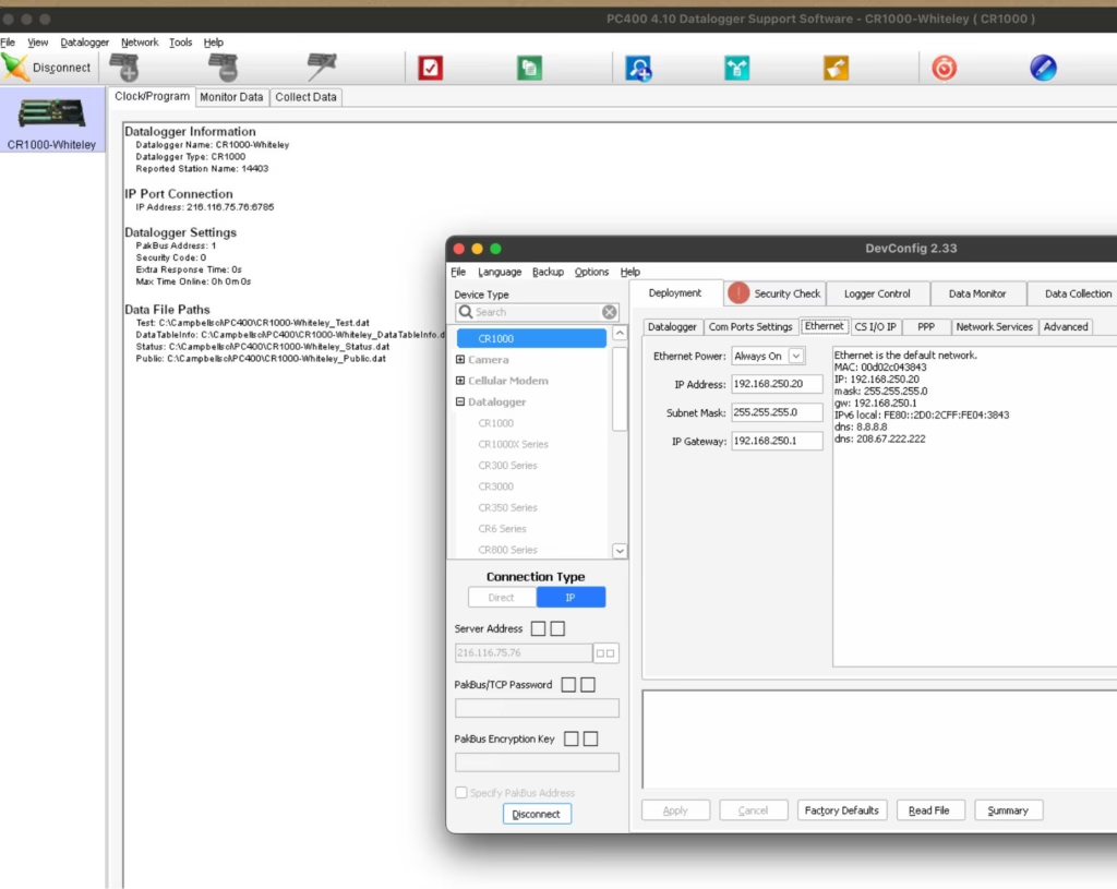
A CRBasic example is available below – I wrote and applied my entire test SMTP program over the Satellite Network! There’s also a more detailed IMT and IP Campbell-specific walkthrough in our previous post.
A Non-Logger! AXIS Cameras
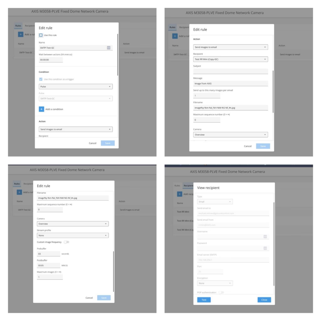
Even though they’re not a logger, AXIS cameras are usually installed next to loggers due security reasons, they also support event-based email delivery with image attachments, which makes integration with the RockREMOTE Mini straightforward. Configure the camera to send images via SMTP to 192.168.250.1:25 with no authentication, and assign it an IP on the Mini’s LAN.

Even though they’re not a logger, AXIS cameras are usually installed next to loggers due security reasons, they also support event-based email delivery with image attachments, which makes integration with the RockREMOTE Mini straightforward. Configure the camera to send images via SMTP to 192.168.250.1:25 with no authentication, and assign it an IP on the Mini’s LAN.
On trigger (motion, schedule, I/O), the camera sends a JPEG image as an email attachment. The Mini receives it, compresses it, and delivers it over IMT to Cloudloop Data, where it is forwarded to your configured destination.
For best results, keep to 1 image per event and avoid high trigger frequency to maintain efficient IMT usage. At the same time, IP can be utilised for live streams if required.
Any Device That Can Send SMTP
The pattern here is simple enough that it applies far beyond branded data loggers. If a device can send a standard SMTP message with a file attachment, it can deliver data over Iridium via the Mini.
That includes Linux systems using mutt or swaks; embedded boards with a TCP/IP stack and an SMTP client library; industrial instruments, PLCs, and weather stations with a built-in email function; or any custom application – a Python script, a shell cron job… Any SMTP client really!
Further Reading
- RockREMOTE Mini overview
- Antenna Mounting and Sky View
- Mini SMTP documentation
- Integrating RockREMOTE Mini with the CR1000
- Cloudloop Data documentation
Discuss Your Integration
Have a specific integration in mind? Our Solutions team works with developers every day to help connect existing equipment over satellite.
If you have a technical question, get in touch via the form, or by emailing hello@groundcontrol.com.
ArduPilot Testing: MAVLink Telemetry Over Iridium Certus 100
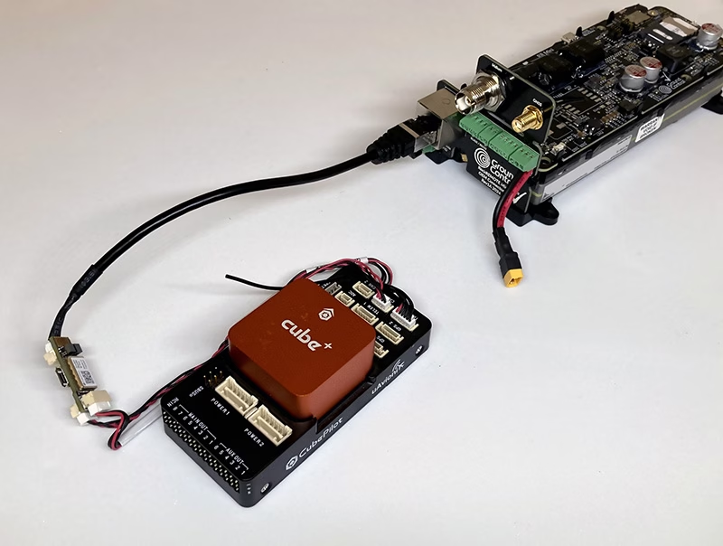
Operating beyond cellular coverage is a reality for many ArduPilot-powered vehicles, and satellite is often the only practical backhaul. Recently, the ArduPilot Development Team (with support from Ground Control) documented MAVLink telemetry performance over Iridium Certus 100 using the RockREMOTE UAV OEM modem. The goal: understand what usable telemetry looks like over a real satellite link, and share configuration guidance the community can replicate.
RockREMOTE UAV OEM is a low SWaP Certus modem designed for OEM integration on unmanned aircraft. It provides an IP data path for BVLOS command and control (C2), MAVLink telemetry, and payload/edge networking when terrestrial backhaul isn’t available.
What the ArduPilot testing looked at
The work, conducted and written up by Stephen Dade, a member of ArduPilot’s Development Team, evaluated MAVLink telemetry reliability and latency over Iridium Certus 100 across multiple connection configurations. In the reported results, MAVLink telemetry was usable and consistent when configured appropriately, with typical round trip latency reported in the sub-2 second range.
Key takeaways from the write-up
- Reliable MAVLink telemetry over Certus 100 (with the right config): The test summary reported measured latencies roughly in the ~600-1600 ms range, with broader observed ranges depending on protocol and conditions.
- Stream rates matter under uplink constraints: The write-up notes Certus 100 uplink limits and recommends configuring ArduPilot stream rates around 2 Hz to stay within available throughput.
- Secure connectivity works best when designed for satellite: High latency/low bandwidth links benefit from VPN patterns optimized for satellite. Ground Control supports architectures that terminate secure tunneling at the gateway, and offers WireGuard where on-link VPN is required.
- Installation can make or break performance: Antenna placement and local obstructions (trees/buildings) had a major impact. Roof height mounting improved results versus a low height suburban placement.
Why this matters for integrators
The documented setup used a representative unmanned systems stack (ArduPilot flight controller, Ethernet bridging, and ground endpoint infrastructure), and the notes are practical for anyone building satellite-enabled autonomy: you can design for predictable behavior, but you have to design around constraints like latency, throughput, and installation quality.
“These results help validate a satellite telemetry approach that can extend operations into truly remote areas, and provide the community with clear configuration guidance.” – Stephen Dade, ArduPilot Development Team
“What’s exciting here is giving builders real architectural choice: lean messaging for efficient telemetry, and IP connectivity when an uninterrupted C2 link matters.” – Alastair MacLeod, Ground Control CEO
Read the full technical write-up
The full methodology, recommended configurations, and measured performance data are here: https://discuss.ardupilot.org/t/ardupilot-and-the-iridium-certus-satellite-service.
Need help integrating Certus100 with ArduPilot?
If you’re looking at satellite-enabled ArduPilot telemetry using Iridium Certus 100, including hardware availability and integration guidance, we’re here to help.
Complete the form, or email hello@groundcontrol.com, and we’ll connect you with our drone specialists within one working day.
The Six Costliest Remote IoT Integration Mistakes (and How to Avoid Them)
Remote IoT looks straightforward until you hit the realities of variable latency, tight data budgets, and devices you can’t easily reach once deployed.
This free and ungated eBook distills the integration pitfalls Ground Control sees most often, plus the practical patterns that help teams go live faster and stay operational long after launch.
It’s written for IoT product and platform teams, systems integrators and solution architects, operations and field deployment leaders, and security/IT stakeholders supporting remote infrastructure.
Read Free eBook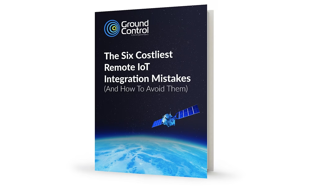
What’s Inside: The Six Costliest Integration Mistakes
1. Security & IT Reality Checks
Satellite links can be strongly encrypted, but risk often concentrates at the handoffs, where data routes from the ground segment into your cloud / application environment.
The eBook outlines common postures (VPN + firewalls, private circuits, or higher-isolation architectures) and the blockers that derail projects late.
Fast takeaway: map the end to end path, choose the security posture deliberately, define ownership, and pre-empt IP range conflicts/timeouts before they become downtime.


2. Interoperability Isn’t Automatic
Remote IoT punishes cellular assumptions. The economics change when every transmission costs power, airtime, and often money.
This chapter shows how teams avoid brittle integrations by designing around constraints: a minimal payload strategy, a clear send policy, and ingestion built for compact messages.
Fast takeaway: prioritize purposeful messages and treat the translation layer as critical infrastructure – version it, test it, and monitor it.
3. The Field Will Prove You Wrong
Coverage maps don’t guarantee performance. Antenna placement, terrain, structures, and foliage create real world RF failure modes.
The eBook clarifies the difference between ‘clear view of the sky’ (LEO satellites) and ‘line of sight’ (GEO satellites), and why confusing these leads to broken installs.
Fast takeaway: validate sky view at the true install height, and test in the actual environment before you scale.

4. Design For Delays, Not Perfection
Message-based satellite IoT doesn’t behave like web or cellular. Systems fail when they assume instant confirmation and tight timeouts.
This chapter explains the ‘accepted vs delivered’ distinction and why retries, buffering, and correct acknowledgements are foundational.
Fast takeaway: use jitter + backoff, implement store and forward properly, and only return ‘success’ after durable storage.
5. Lifecycle and Remote Device Management
Remote device management traffic competes with mission data – reboots, logs, config reads, and updates all consume power and paid data.
The eBook covers how teams avoid slow-motion failures by separating ‘alive’ from ‘healthy’, controlling configuration drift, and planning staged updates.
Fast takeaway: treat configuration like code, budget for ops traffic, and design a real end of life workflow.

6. Data Discipline in Constrained Connectivity
Most systems can produce far more telemetry than anyone will ever use, and ‘send everything’ is the fastest way to lose control of battery life and budgets.
This chapter gives practical patterns like exception reporting, edge summaries, payload compaction, and ruthless prioritization so you protect what matters most.
Fast takeaway: define the smallest information set that drives decisions, then budget size/frequency/retry rules by priority tier.
Key Outcomes You Can Expect
By the end, you’ll be able to spot the integration choices most likely to cause schedule slip and rework, set realistic expectations for latency, delivery confirmation, and retries, and build payload and send policies that scale economically.
You’ll also learn how to reduce truck rolls by designing lifecycle management in from day one, and how to pressure test your deployment plan before you scale it.
The core theme throughout is simple: design for operations, not just installation.
Read the eBook before you make your next integration decision
Get the PDF immediately (ungated). It covers security handoffs, interoperability, field RF realities, latency/retries, device lifecycle, and data discipline.
Read Free eBookWant help pressure testing your integration plan?
If you’re planning a remote deployment and want to validate your architecture, data budget, or rollout approach, we can help you identify risk early – before it becomes field rework.
Contact Our ExpertsFAQs
It’s written for remote deployments where constraints matter most – satellite and hybrid deployments in particular – but the integration lessons apply broadly to any system where latency, cost, power, and field access are real constraints.
Yes. Several chapters focus on operational issues that appear after launch (retries, lifecycle management, configuration drift, and data discipline).
Yes. Each chapter ends with concrete takeaways (e.g., security mapping and ownership, field testing non-negotiables, ‘slow link’ checklist, and data discipline checklist).
Have a remote IoT project to discuss?
No need to contact us to read the eBook – but if you want to chat about your remote IoT project, we’d love to hear what you’re working on.
Complete the form or email hello@groundcontrol.com with your application details, and we’ll connect you with one of our expert team to see if we can support your goals.
Using a Campbell CR1000 (CRBasic) with a RockBLOCK RTU (SBD Device)
In today’s rapidly evolving landscape of remote monitoring and data acquisition, integrating reliable communication systems is crucial. RockBLOCK RTU integration provides a robust solution for industries such as environmental monitoring, agriculture, and industrial automation, ensuring seamless data collection and transmission from remote locations.
In this post, we will discuss the integration of RockBLOCK RTU, and show how we have configured it to work with the Campbell Scientific CR1000.
What is RockBLOCK RTU, and Why Does it Matter?
RockBLOCK RTU is a low power, rugged, waterproof remote I/O device designed for permanent installation in harsh outdoor environments. Utilizing Iridium’s Short Burst Data (SBD) satellite service, RockBLOCK RTU supports two way communication anywhere on the globe, ensuring reliable connectivity even in the most remote locations.
Combined with Ground Control’s Cloudloop Services Suite (Subscription Manager and Cloudloop Data), RockBLOCK RTU allows users to land, visualize, store and forward their data in a flexible environment that is easy to integrate with. Aside from the Cloudloop suite, the RockBLOCK RTU supports physical analogue and digital inputs and outputs that can be locally programmed to trigger based on thresholds or actions.
How we integrated the CR1000 with the RockBLOCK RTU
Step 1: Understanding the Data Format
The RockBLOCK RTU system supports a structured data format that includes:
- Channels CH16 to CH31 mapped to General Purpose Sentence (GPS) data
- Each channel supports 5-digit values (00000 to 65533)
- Comma-separated values within the data string.
Example Data String:
STXGP0,…,GP15,ETXCHECKSUMCRLF

STX = 0x02 (HEX) – (Start of Sentence)

ETX = 0x03 (HEX) – (End of Sentence)

CHECKSUM = Between STX and ETX (Excluding them) formatted as 5 digits, zero padded

CR = 0x0D (Carriage Return)

LF = 0x0A (Line Feed)

STX00000,00000,00000,00000,00000,00000,00000,00000,00000,00000, 00000,00000,00000,00000,00000,00000,ETXCHECKSUMCRLF
Step 2: Configuring Cloudloop for RockBLOCK RTU
- Create Channel: Map channels 16 to 31
- Type: Analog Input
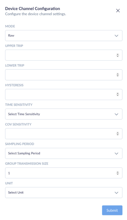
- General Purpose Data String-related Device Channel Configuration:
-
- Mode: RAW
- COV (Change of Value): 0 for no COV, 1 for COV enabled
- Group Transmission Size: Minimum 1
Note: Channels should get created automatically in Cloudloop Data once valid data is passed through, although each channel can still be re-configured or pre-configured via Cloudloop Data. It is also important to note that the RTU needs to be active, powered and have a good view of the sky for it to receive the channel configurations via the satellite link.
Example of Cloudloop Data Insights
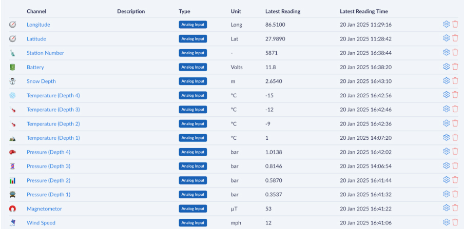
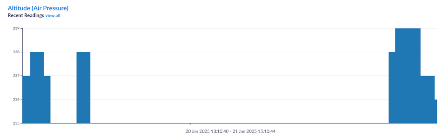
This screenshot showcases the Cloudloop platform’s data visualization capabilities when integrated with RockBLOCK RTU. Each channel represents a specific parameter being monitored, such as location (latitude and longitude), battery voltage, snow depth, temperature at various depths, pressure readings, and wind speed. All of which can be named and customized per your requirements. we have chosen the aforementioned parameters for illustration purposes.
Step 3: Setting Up Communication
- Connect Serial COM2 TX to RX (PINK) on RockBLOCK RTU
- Set baud rate to 19200, which is the default for RockBLOCK RTU
Step 4: Implementing the CRBasic Code
The CRBasic code constructs data strings in stages to accommodate memory constraints. Temporary strings (TempStr variables) are concentrated to form the final 16 channel DataString.
Example CRBasic Code:
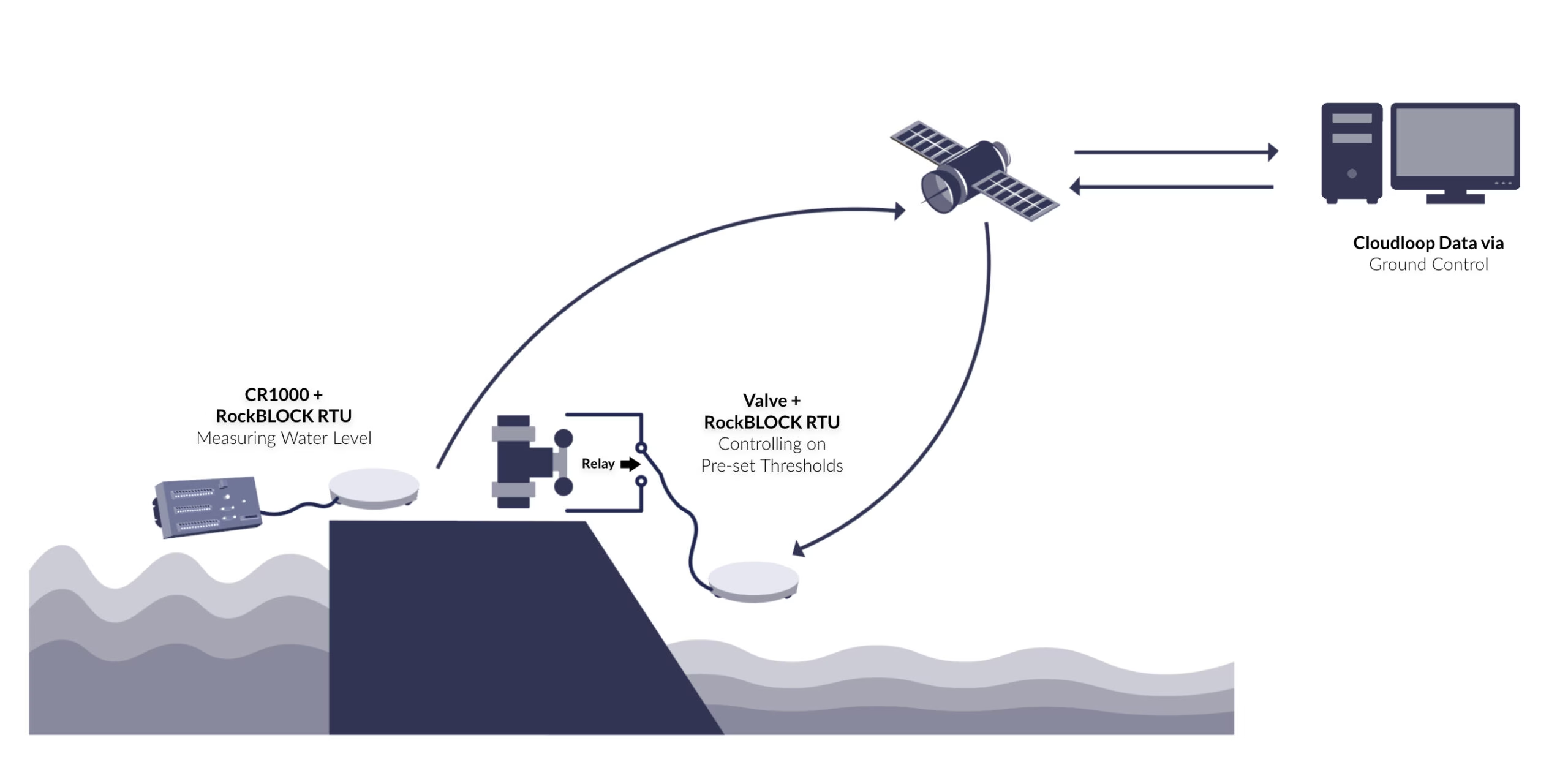
This integration will allow up to 16 sensor values to transmit from the CR1000 through the RockBLOCK via SBD to Cloudloop Data (Insights) and optionally forward to a chosen destination. By introducing Cloudloop Data in the middle of the data transfer, you allow for much more than just data display or remote configuration, but the ability to set email alerts depending on thresholds and even set actions – such as controlling a separate RockBLOCK RTU anywhere in the world autonomously.
Imagine a scenario where one RockBLOCK measures the water level at a dam, and a second RockBLOCK controls a valve on pre-set thresholds.
Ready to get started?
If you’re interested in learning more about how RockBLOCK RTU can transform your remote monitoring capabilities, contact us for a personalized consultation.
Also, have a look at our RockBLOCK RTU documentation website.

Michael Mitrev – Solutions Architect
Graduating with a 1st Class Degree in Computer Systems and Networks Engineering and joining the team in 2024, Michael has been closely involved in the development of the RockREMOTE Mini and is passionate about its growth and success. He’s also contributed to the RockBLOCK RTU, ensuring both devices integrate seamlessly with data loggers to create highly sought-after solutions – primarily focusing on testing with Campbell’s CR1000.
Transform your CR1000 into a powerful remote monitoring solution
Whether you’re tracking snow depth, water levels, or environmental conditions, the RockBLOCK RTU + Cloudloop integration offers reliable, global data delivery.
Complete the form, or email hello@groundcontrol.com for expert advice; we’ll respond within one working day.
Integrating RockREMOTE Mini with the CR1000 Data Logger
In this integration, we’re bringing together two proven technologies to solve a common challenge in remote monitoring: reliably transmitting environmental data from locations with no terrestrial connectivity.
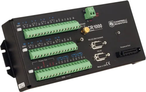
The Campbell Scientific CR1000 is a widely used data logger known for its durability and flexibility in harsh environments. By pairing it with the RockREMOTE Mini, a compact satellite device simultaneously supporting both IP and IMT communication over the Iridium Certus 100 network, we enable robust, low-power data transmission from virtually anywhere on Earth. This document outlines how the integration works, the benefits of each device, and the steps to get a system up and running.
Note: while our testing was with the CR1000, this solution will also work with the newer Campbell Scientific data logger models: CR1000x and CR1000Xe.
Why the Campbell Scientific CR1000 Series is so Prolific
The CR1000 and its successors are renowned for their versatility, reliability and robust performance in harsh environmental conditions. They support a wide range of sensors and communication protocols, making them the go-to choice for remote sensing applications. With CRBasic programming, data collection and processing can also be customized to meet specific needs, enabling bespoke, efficient, and reliable monitoring in a range of diverse scenarios.
Whether monitoring water quality or glacier temperatures at Mt. Everest, their ability to collect and process data has made them a cornerstone of environmental monitoring systems worldwide.
When paired with RockREMOTE Mini, the CR1000 becomes a truly global resource, capable of operating autonomously in even the most remote and harsh locations. By combining these two devices with a modest solar solution, users can deploy a fully self-sustaining system that ensures reliable data monitoring and access anywhere in the world, even in areas where no terrestrial networks are available.
Introducing RockREMOTE Mini
RockREMOTE Mini is an efficient and compact satellite communications device designed for connecting devices where terrestrial networks are unavailable. It utilizes the Iridium Certus 100 service and simultaneously can send data over both IMT (Iridium Message Transport) and IP (Internet Protocol). This allows you to take advantage of the easy and standards-based approach of IP for a PoC and then leverage the efficiency of IMT when scale is required.
With both Serial Communication (RS232/RS485) and Ethernet (with PoE+) available, the Mini is straightforward to integrate. The Mini’s Sleep pin allows for dynamic power management, which is particularly beneficial for solar-powered or battery-operated deployments. The Mini has a very low standby draw of only 300 mW while still being able to receive communications. It can be advantageous to put the Mini to sleep when power is at an absolute premium. An inbuilt GNSS receiver also allows the Mini to provide a time source for multiple connected devices over SNTP.
While it’s very straightforward to integrate the RockREMOTE Mini with your hardware, it is equally simple to get or view your data with our Cloudloop platform. You can use Cloudloop Data to view the data directly or have Cloudloop forward the data to your server. Crucially, Cloudloop functions as a translator between Iridium’s IMT protocol and many of the web standards that you are familiar with, for example, HTTP webhook, Azure Queue, MQTT, ThingsSpeak, AWS SQS & S3, to name a few. This means that integration is fast and efficient, allowing you to utilize the most efficient protocol for the satellite portion of the network and the most convenient one on the server side.
For IP, Cloudloop NOC provides clear packet tracing and troubleshooting, including the ability to set Inbound and Outbound firewall rules to ensure your device is protected and set up for your requirements.
Cloudloop Device Manager can also be used to manage devices by updating their firmware and configuration over the air, ensuring they remain up-to-date without requiring physical access.
Iridium Messaging Transport (IMT) vs IP
We have discussed using the most appropriate transport method for different parts of the network. This is crucial for keeping airtime costs down while also allowing for easy development. The table below gives a quick overview of the differences. Cloudloop enables you to benefit from the upsides of both.
| Iridium Messaging Transport (IMT) | IP-Based Communication | |
|---|---|---|
| Data Size | Small to medium data packets (max 100 KB per message) | Larger data transfers (unlimited size) |
| Cost | Lower cost per message (no headers, data only) | Higher cost per message (headers, TCP/UDP) |
| Use Case | Periodic sensor readings, status updates, scheduled reporting, configuration changes | Real time monitoring, program updates, large chunks of data transfers, and constant reporting |
| Integration | Requires CRBasic formatting to implement AT commands | Seamless – plug and play |
RockREMOTE Mini operates over Iridium’s Certus 100 Network, offering speeds of 22 Kbps up and 88 Kbps down to the remote terminal. IP is ideal for quick and easy integration with existing systems, leveraging standard TCP/UDP protocols, as well as Outbound, Inbound Port Filtering, and Port Forwarding.
In contrast, IMT is a message-based protocol that transmits data in Base64 format, eliminating the overhead of headers and limiting the message size to 100 KB. While IP requires no additional development work, IMT involves creating a CRBasic program to communicate with the Mini over a serial port using AT commands. This can add complexity, but it provides complete control over the transmitted data, making it a cost-efficient option for low-bandwidth applications.
For example, if an application involves transmitting temperature readings from a dozen sensors every hour, IMT would be the most cost-effective option. On the other hand, if you need to update the CR1000’s program remotely, retrieve a whole day’s worth of data, or monitor the data constantly, IP would be the better option. This highlights the flexibility of the RockREMOTE Mini since it can communicate both over IP and IMT at the same time.
How we Integrated the RockREMOTE Mini and CR1000
1. Connections:
- Connect the Mini’s brown Sleep pin to the CR1000’s C1 for power control
- Connect the Mini’s orange 0V-REF pin to the CR1000’s Ground
- Temperature sensor to 1H and 1L on the CR1000.
2. Serial Communication (for IMT):
- Mini communicates with the CR1000 via COM2 at 115200 baud
- Connect TX (CR1000) to RX (Mini) and RX (CR1000) to TX (Mini).
3. Ethernet Communication (for IP Inbound/Outbound Port Configuration):
- Connect the Mini’s Ethernet port to the CR1000 or a local switch
- Assign a static IP to the CR1000 in the Mini’s network range (e.g. 192.168.250.2).
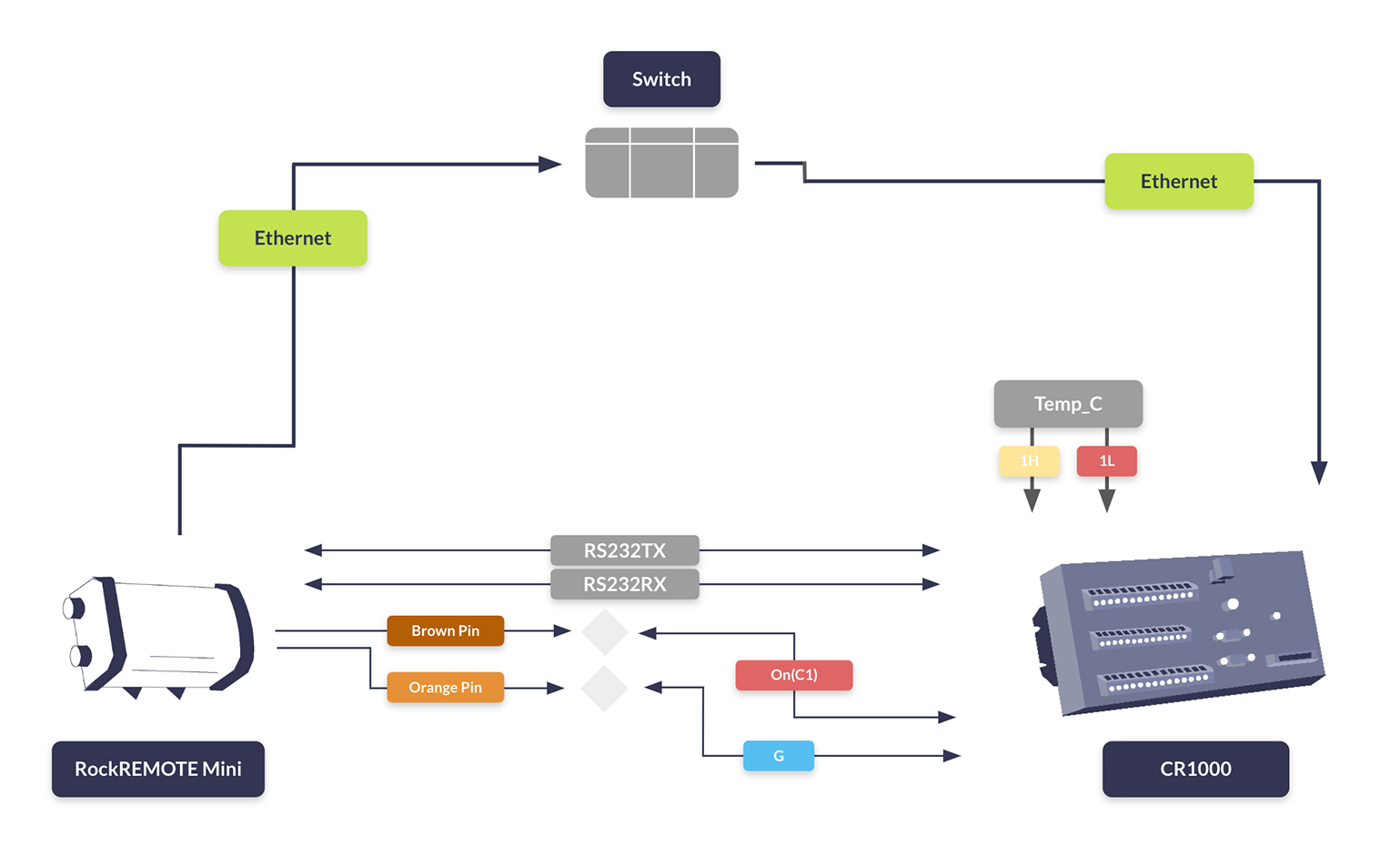
Whether you’re optimizing for cost, scalability, or accessibility, the RockREMOTE Mini and CR1000 can deliver a tailored solution that meets your needs.
This CRBasic code snippet runs on our CR1000 Logger, managing the Mini’s power state based on temperature thresholds. Initially, the Mini is in Sleep Mode. When the upper temperature threshold is exceeded, the Mini wakes up and begins transmitting data. It continues transmitting until the temperature drops below the lower threshold, at which point it returns to Sleep Mode.

Michael Mitrev – Solutions Architect
Graduating with a 1st Class Degree in Computer Systems and Networks Engineering and joining the team in 2024, Michael has been closely involved in the development of the RockREMOTE Mini and is passionate about its growth and success.
He’s also contributed to the RockBLOCK RTU, ensuring the device integrates seamlessly with data loggers to create highly sought-after solutions – primarily focusing on testing with Campbell’s CR1000.
Ready to get started?
If you’re interested in learning more about how the RockREMOTE Mini can transform your remote monitoring capabilities, contact us for a personalized consultation.
Complete the form, or email hello@groundcontrol.com, and we will reply within one working day.
Introducing Ground Control’s Satellite IoT Gateway
Imagine you’re the manufacturer of industrial equipment — perhaps you supply power generators to war zones, or monster excavators to mining projects, or perhaps you make sensors for monitoring pipelines.
The equipment that you produce is inherently big and complex — which means that it’ll be packed with gizmos and sensors to monitor its health, performance and to detect faults/errors.
If a sensor fails in the forest, and nobody is around, does it make a sound?
Herein lies the problem. Your equipment isn’t around the corner — you can’t just pop over to check it’s ok. If it’s truly remotely deployed, it may require several days travel and a helicopter to check!
Clearly this isn’t a sustainable or practical solution — so what about remote monitoring? It’s unlikely that you’ll be within cellular coverage, and if you are it’s likely to be patchy and unreliable (it’s like that even in the middle of London sometimes)!
In this instance, the only viable option you have for remotely monitoring your equipment is via satellite. Today, there’s a multitude of satellite operators and terminals available, each with their respective pros/cons in respect of physical size, operating cost, power requirements, communication speed and bandwidth etc.
For our hypothetical scenario, let’s assume we make monster excavators used to extract lithium from remote Australian mines. They’re super-computers on wheels and are packed with sensors, measuring things like: temperature, pressure, vibration, movement and location. There’s a ready supply of power but physical space is limited. Being able to monitor this data in real-time is invaluable for things like performance and safety monitoring.
Introducing Ground Control’s RockREMOTE
The RockREMOTE is an Iridium Certus IoT terminal, providing both IP connectivity and IMT-based messaging from anywhere on the planet. Its IoT Gateway enables easy integration with other equipment and applications through the lingua-franca of the IoT industry — MQTT.
How do we connect the RockREMOTE to a monster excavator?
In our scenario, we’ve got an onboard network connecting all the sensors to a central data logger which stores the sensor readings. The sensors themselves speak to the data-logger via the industry-standard CAN bus protocol as is commonly used in the automotive industry.
The data logger is simply connected to the RockREMOTE via Ethernet cable.
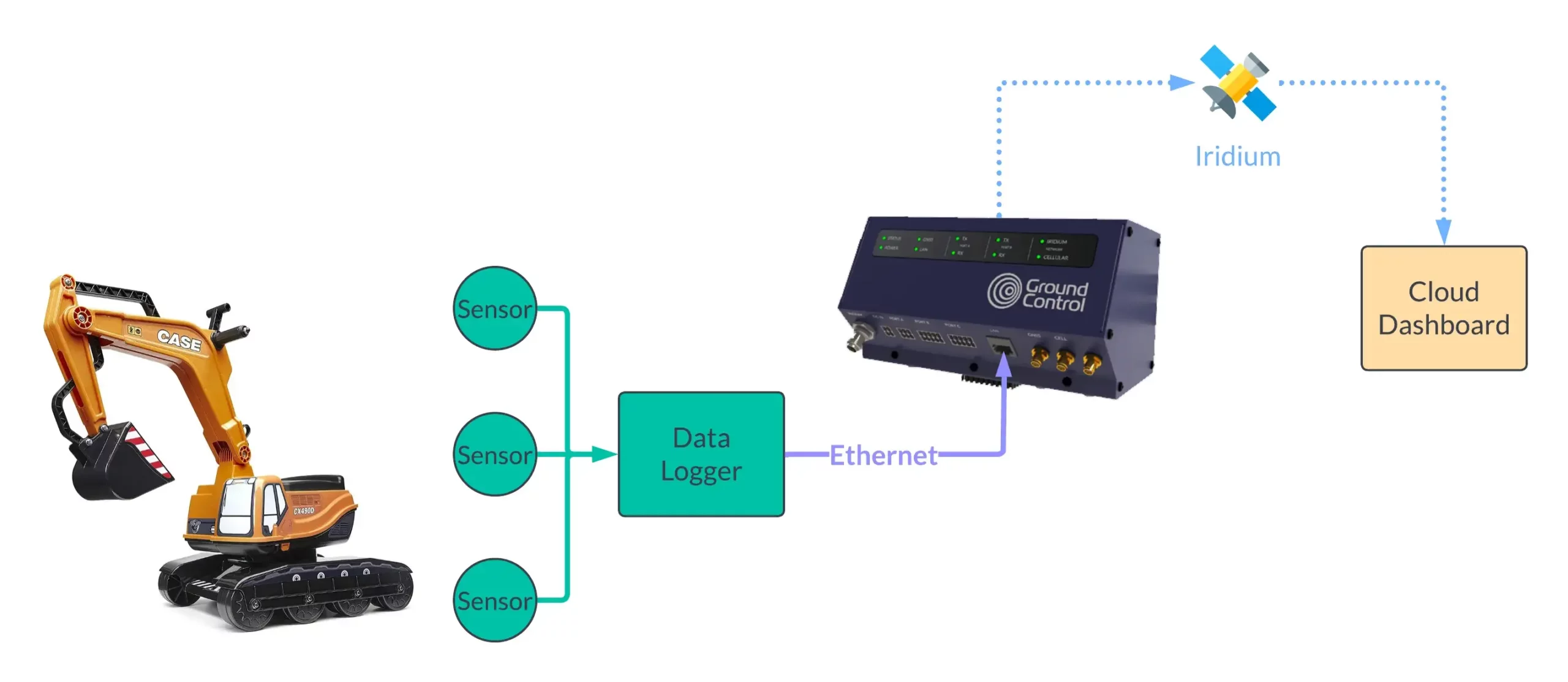
Yes that’s a child’s toy — no expense spared artist’s impression showing the system end-to-end
Data Logger > MQTT > RockREMOTE (IoT Gateway)
So we’ve got our readings gleaned from the onboard sensors; they’re currently stored in a simple database on our data-logger. This is a proprietary system developed in-house, so we’ll need some developer-smarts to send the data to the IoT Gateway on the RockREMOTE.
Side note: it’s at this point that everyone’s system will vary. In the event that you’re not already utilising MQTT, some development work will be unavoidable. Fear not: due to the ubiquity of MQTT, it’s very widely supported and there’s established libraries for most platforms and programming languages.
Our data-logger runs Linux so we have a multitude of tools at our disposal; the simplest and easiest being a basic Python script (as shown below):
This snippet will diligently send the sensor readings to the IoT Gateway every 60 seconds. That’s it — pretty cool 😎
What do you mean that’s it — we’ve not even mentioned Satellites?
This is where the RockREMOTE IoT Gateway comes into its own!
RockREMOTE x IoT Gateway
So let’s pop the proverbial hood and let’s see what’s actually going on here.
On the surface, IoT Gateway exposes a standard MQTT broker — nothing special or proprietary — this means any existing MQTT client/library can connect and publish messages.
Security specialists: on this interface it utilises basic username/password authentication; so there’s no certificate authentication with which to concern yourself. No one wants to charter a helicopter to update an expired certificate, and if the monster excavator is physically compromised – well, you’ve got bigger problems to worry about…
There’s no restriction to the message payload that you publish — you can send text or binary; anything you like — most popular for IoT applications is JSON or Protobufs. The only limitation is that the total message size must not exceed 100 Kb — more on this in a second.
Not sure what MQTT is?
It’s pretty straightforward. MQTT is an industry standard which describes a simple Pub-Sub protocol whereby: clients connect to a broker and PUBLISH messages — other clients connect to said broker and SUBSCRIBE to receive the messages when published — that’s pretty much it!
To keep things organised it utilises the concept of TOPICS — whereby a message is published to a named topic — typically these take the form of a directory structure (e.g. /site01/sensor10/temperature) but you can use anything you like.
It does a few other things, but that’s all you need to know for now!
In the same way there’s no restriction to the message payloads, there’s also no restriction to the topics that you use. This is super convenient if you’re migrating from an existing MQTT solution — no need to change your topics!
So to recap: you can use any MQTT client/library, send any message payload to any topic you like. It’s almost as if Ground Control have taken a monster excavator to any possible barriers or hurdles to using this!
C’mon — what about the satellites?
So we’ve PUBLISH’d our inaugural “Hello World” message to IoT Gateway — what happens next? How do I get hold of these beautiful ones and zeros?
It’s magic. Or it may as well be, we don’t actually need to do anything more — the IoT Gateway takes care of all the heavy lifting. But since you’ve come this far — let’s dig into the wizardry…
The RockREMOTE is an Iridium Certus 100 IoT terminal. This means that it can talk to the Iridium satellite network to send/receive data. It has truly global coverage and works anywhere on the planet at any time of the day.
Zeroing in further, the IoT Gateway makes use of the brand new Iridium Message Transport (IMT) service. Read the deep-dive into how IMT works and how it differs from other IP Connection-based services.
In essence, this is a message-based service for sending/receiving messages up to 100 Kb. You’re only charged for the data you successfully transmit, so you’re not charged for protocol overhead, handshaking or bloat 😎
Sending the Message
Anything you PUBLISH will be automatically packaged and sent to space. IoT Gateway takes care of managing the connection, message queuing, retries etc — truly fire-and-forget!
Thud!
That’s the sound of your “Hello World” message landing down to earth.
This time instead of being in a remote Australian lithium mine; it’s in sunny Tempe, Arizona (where Iridium’s ground station resides). From here it’s whisked to Ground Control’s omnipresent platform, Cloudloop.
Your message, still cold from its brief stint in space, is reconstituted and published to their secure cloud-based MQTT broker (not to be confused, with the broker mentioned earlier, that resides on the RockREMOTE).
Again, this completely standard MQTT interface can be securely connected to with any MQTT client or library, allowing your cloud-application to consume the messages published from IoT Gateway.
Back to the monster excavator…
Recap: we’ve used a Python script running on our data-logger to relay sensor data (via MQTT) to the IoT Gateway every 60 seconds. For the alert readers, you’ll recall this data was published to the lithium/truck01 topic. The data has gone via satellite and has now been re-published to the MQTT broker residing in Cloudloop.
We’d now like to present the sensor data in real-time on a dashboard screen we’ve got setup in the office. For this, we’ll need to SUBSCRIBE to the relevant topics to get this information automatically pushed to it.
We’ve got two options — use an existing IoT Dashboard (e.g. Thingsboard) or create something ourselves. We’ll take a look at how we might get the data ourselves here.
To consume the messages from Cloudloop MQTT:
Side note: the message was technically published to iot/ACCOUNT-ID/lithium/truck01 — this is because it’s a multi-tenanted environment and the prefixing nicely provides account-segregation.
In this scenario, we’ve been working with a single excavator — but there’s nothing stopping this working with multiple. You can easily see by changing the topic name (e.g. cobalt/truck32) we could support multiple sites and multiple excavators 😎
What about sending messages to the monster excavator?
So far, we’ve only spoken about data originating from the monster excavators (Mobile Originated in satcom parlance) — but what about sending messages to the excavator (i.e. Mobile Terminated)?
No problem, it works in exactly the same way — just in reverse.
Simply PUBLISH a message to Cloudloop MQTT and it will be sent via space and picked up by the IoT Gateway; the data-logger would just need to SUBSCRIBE to that particular topic to receive the message.
Would you like to know more?
Whether you’re an engineer or you’re interested in learning more about IMT, the IoT Gateway, or the RockREMOTE, please call or email us, or complete the form, and we’ll make sure you’re connected.
How Iridium Messaging Transport (IMT) opens up new IoT possibilities
Iridium Messaging Transport (IMT) was launched on 21st December 2022, and in Iridium’s own words, it’s “a two-way cloud-native networked data service optimized for use over Iridium Certus and designed to make it easier to add satellite connections to existing or new IoT solutions. IMT provides an IP data transport service unique to the Iridium network, designed for small-to-moderate-sized messages supporting satellite IoT applications.”
So what does this mean for the often overlooked, but nonetheless critical world of small-to-moderate-sized IoT messages?
For those of you wanting to reliably send/receive small amounts of data from anywhere on the planet, the only truly tried and tested solution is Iridium Short Burst Data (SBD) that enables you to send/receive messages up to around 300 bytes (yes, bytes)!
In general, describing anything as being small-to-moderately sized is not something to shout about. But in the world of IoT and M2M it’s not how big your payload is, it’s what you do with it…
Constraint breeds innovation — if you’ve only got 300 bytes to play with, you start to think creatively and use all sorts of tricks and techniques to cram as much information in as you can! There’s countless companies using SBD to do incredibly cool things (hello, ybtracking.com).
However there’s a limit — no matter how much you try, you cannot squeeze a photograph into an SBD message; nor can you squish in a whole weather GRIB file (trust me, I’ve spent the last 10 years trying)!
We’re gonna need a bigger boat…. enter stage left: Iridium Certus.
The Iridium Certus 100 service is the next-size-up for people looking to send/receive larger volumes of data via satellite. There are differences beyond speed and data limitations: Certus 100 provides a full-blown IP-connection and SBD is Message-based; not to mention the larger form-factor and antenna requirements, and cost etc.
What’s a satellite IP connection anyway? Simply put, it’s a full-on (albeit very slow) Internet connection, just like the one you’re using right now. Except instead of being a super-fast, fibre-optic, giga-bit connection, it’s a measly 88 Kbps — yes, there’s our old friend bytes again.
(Faster Iridium Certus service classes are available, up to a heady 700 Kbps using Certus 700 — but the entry-level Certus 100 service is best suited for IoT applications).
And Message-based? To save on words, it’s essentially an SMS text message you’d send from your mobile phone. You want to send “Hello World” and that’s all you send — there’s no superfluous headers, handshakes or protocol bloat (I’m looking at you, Mr IP Connection).
Analogy: Message-based communications is like calling up a friend and leaving a message on their answerphone; once they’ve listened to your message; to reply they call you back and leave you an answerphone message.
While this could be considered a crude form of two-way communication; it lacks the dynamism, flexibility and spontaneity of a telephone call — where both parties can freely communicate, interrupt without delay (i.e. IP Connection-based).
So to recap: Iridium Certus is faster and capable of sending loads more data (compared to the minuscule 300 bytes that SBD offers) — the kicker however is you have to contend with talking proper big-boy TCP/IP; this means latency, two-way handshakes, retries and failed transmissions.
One thing that you can be certain of: if you’re sending data from the middle-of-nowhere, up into space, to a satellite, back down to earth and then onto the Internet; and back again — there’s going to be latency and packet-loss. This is true of the Internet connection you’re using now, but this all happens in the background and you never notice anything — however, when you’re on a very slow connection (and you’re paying for every byte you send and how long you’re connected) — you’ll soon notice!
So the solution? Use a Message-based service, where you just pay for the actual payload that you send and only when it’s successfully transmitted. Er, what, like SBD? Yes exactly.
Enter stage right: Iridium Certus Message Transport (IMT).
IMT is the best of both worlds — Message-based service utilizing Iridium Certus 100 to facilitate, drum-roll please… sending/receiving messages up to:
One-hundred-thousand-bytes (yes, 100,000 bytes)!
(Finally, something about which those with a small-to-moderate-sized payload can rejoice)!
This is a massive increase in message size, finally making it feasible to send larger amounts of data from anywhere on the planet. You’re not going to be able to browse the Internet or stream Netflix — but your remotely deployed IoT application, monitoring some hypothetical oil and gas pipeline will now be able to send more data. Which in turn might facilitate additional sensor readings, greater data resolution or even low-res photographs if it detects suspicious activity — the sky’s the limit!
IMT is pretty cost-effective, you’re only charged for the data you send: price plans start from 25 USD/month, and typical data usage costs 10 USD/MB.
From SBD to IMT
The pathway to IMT for existing SBD applications (that use something like Ground Control’s RockBLOCK) is pretty straightforward.
As mentioned earlier, SBD and Certus 100 are not like-for-like comparable — Certus 100 is bigger, more expensive, requires more power and a bulkier antenna compared to its short-burst brethren (although both are still considered microscopic compared something like VSAT).
So if you’re building an autonomous-flying plane for delivering medicine across Africa (hello, Zipline) — you’ll probably want to stick with SBD. However, if your remote IoT application is not as constrained, IMT might just be the thing you’ve always longed for.
Engineers integrate with SBD by sending simple AT commands via a serial interface — however, in contrast, IMT is not directly exposed by default on Certus 100 terminals. It’s up to the individual terminal manufacturers to decide if/how they want to expose it.
At time of writing, only two manufacturers had IMT solutions ready for their terminals. And Ground Control is one of them: both the original RockREMOTE and the new RockREMOTE Rugged are IMT-ready.
RockREMOTE, utilizing our IoT Gateway, exposes IMT messaging through the lingua-franca of the IoT industry – MQTT. The proposition is simple: talk MQTT in the field (e.g. from your microprocessor, PLC, Arduino or RPi) to the RockREMOTE and your message will be magically whisked off (via space) and arrive at their Cloud MQTT broker ready to be consumed by your application/ dashboard — effectively end-to-end MQTT.
So from an integration perspective, while it’s not quite a drop-in for SBD — it’s not far from it. By using an industry standard MQTT interface, it’s possible to send/receive messages with just a few lines of code.
Let’s just replace all existing IP connections with IMT – simple, right?!
Alas, it’s not necessarily that straightforward.
Imagine you’re coming at IMT from an existing IP connection-based solution; maybe you’re already using Viasat IoT Pro or maybe you’re moving to Satellite IoT from the world of Cellular IoT.
The good news is, if you’re already using MQTT, the move is likely to be a piece-of-cake with a device like the RockREMOTE. All you’ll need to do is update the destination of your MQTT broker to point to the RockREMOTE.
If you’re using something like HTTP GET/POST or FTP — it’s pretty simple to take the data you would have sent via these means and package it up to send via MQTT instead. One of the great things about MQTT is that there’s no prescribed message format — send Text, Binary, JSON or Protobufs etc.
Finally, what about if you’re doing something more complex, for example using another application or protocol that expects an interactive two-way IP connection (e.g. SSH, SFTP, TCP/IP sockets, Web browsing etc)?
In short, IMT isn’t going to work for you. Message-based communication is perfect for asynchronous communication – fire-and-forget — it isn’t suitable for scenarios that require synchronous communication — (see again the answerphone analogy).
Unfortunately, if you have to use this type of synchronous communication; your only option will be to continue to use an IP Connection.
But there’s a glimmer of hope. Some devices, like the RockREMOTE, are able to support both message-based communication (using IMT) as well as IP connection — so you have the flexibility to use either methods (or indeed, both), depending on the type of communication you want to undertake.
Would you like to know more?
Whether you’re an engineer and want to talk to Dan (or someone like him!), or you’re interested in learning more about IMT, the IoT Gateway, or the RockREMOTE, please call or email us, or complete the form, and we’ll make sure you’re connected.
Ground Control Delivers SBD Data to AWS Platforms
Whatever the function, Iridium short burst data (SBD) is a tried, tested, and cost-effective method of getting IoT data back to you via satellite from anywhere on Earth. Rock Seven (now trading as Ground Control) and Amazon Web Services (AWS) have now taken this one step further by allowing the data to be transported directly into Amazon Simple Queue Service (SQS) queues. This is done via a CloudFormation stack which creates the customer’s queues and takes care of cross-account permissions.
This new offering saves developers time in dealing with TCP sockets, byte-arrays, and proprietary protocols. While there may be a degree of background work, Ground Control can help, with minimal strains on resource times. It also helps people already using AWS to easily integrate with Ground Control devices.
Ground Control CTO, Ric Searle, said: “We’re already expert at leveraging AWS to build and scale our own IoT applications. Broadening this offering to help our customers get data into their own applications just makes perfect sense, and really speeds up application development. Our customers can focus on their business logic, rather than wasting effort re-engineering the data ingestion layer.”
Ground Control customers are already adopting this new offering. A recent example is an established Agritech organisation working with farmers in remote areas. They are using Iridium Edge and RockBLOCK products supplied by us to report on critical crop data from remote locations. To add to this, the needs of this customer were urgent as they were constrained by seasonal requirements.
Ground Control helped to integrate the global reach of Iridium, robust equipment such as the RockBLOCK and Iridium Edge, and the cutting-edge processing inside AWS – and gave the customer the solution they needed in record time.
In summary, this collaboration shows that:
- SBD is ideal for M2M/IoT applications
- Ground Control can help get your IoT data into the Cloud
- SBD equipment typically has small form factor and low power requirements
- Ground Control are Iridium SBD and AWS specialists
- Iridium SBD provides truly global coverage for IoT requirements.
Is Iridium SBD right for your project?
We are SBD experts; we’ve been designing and manufacturing devices that work on this network since 2005, and we’re very well placed to help you find the right product and airtime for your requirements.
Complete the form, or if you prefer to speak to someone directly, call us on +44 (0) 1452 751940 (Europe, Asia, Africa) or +1.805.783.4600 (North and South America). Whether you’d like a quote or just friendly and impartial advice, we’re here to help.
Global Satellite Communication for Qwiic Projects from SparkFun
The SparkFun Qwiic Iridium 9603N has been developed in order to provide a method for Short Burst Data (SBD) global communication for Qwiic projects via the Iridium Satellite Network. If a customer is prototyping with I2C and is looking to transmit short messages outside of GSM or WiFi networks or when said networks may not always work, this could be the answer.
SparkFun’s Qwiic Connect System uses 4-pin JST connectors to quickly interface development boards with sensors, LCDs, relays and more. The Qwiic Iridium 9603N module hosts a 9603N modem and also provides an antenna and power supply requirements. The modem’s serial interface is translated into I2C commands by the ATtiny841 microcontroller.
With a clear view of the sky, SparkFun boasts: “Sending and receiving messages to the Iridium network is as easy as sending I2C commands from your RedBoard over a Qwiic connector. The Arduino library walks you through sending messages to the Iridium network using your Qwiic Iridium 9603. Ground Control’s online portal, Cloudloop, and APIs allow you to send messages from the Iridium satellite network to your modem.”
Ground Control CTO, Ric Searle said: “It’s great to see Ground Control services being used in SparkFun’s experimental products to further development in IoT and SBD – SparkFun is a key partner and US reseller of our RockBLOCK products. The Qwiic board is a great little piece of kit and we look forward to assisting in the further development of the Qwiic Iridium 9603N and its certification”.
Currently the Qwiic Iridium 9603N is being sold under the SparkX banner. SparkX hosts products that have been rapidly produced so that customers have access to the most cutting-edge technologies. However, because they have yet to be “polished” to completion, SparkFun manage a peer-to-peer forum for like-minded individuals to gain support and share knowledge.
SparkFun was founded on the ethos of making electronics more accessible to everyone. Products and resources have been designed with this premise at its heart. Its portfolio of over 2,000 source components and widgets is impressive and is complemented by curriculum, training, and online tutorials to ‘demystify the wonderful world of embedded electronics’.
Get in touch
Having partnered with satellite network providers such as Iridium and Inmarsat for well over a decade, we have access to competitively priced tariffs, and can also be very flexible in terms of bundled data.
So if you are working on an IoT project and would like some no pressure, objective advice, simply fill in the form and one of our expert team will get back to you.
Maker Buoy: Drifting buoy equipped with the RockBLOCK
The Maker Buoy is a low-cost, Arduino-based, solar-powered and open-source drifting buoy available to purchase ready-made or for the end-user to construct themselves following simple instructions.
The goal is to provide a tool so that we can gain invaluable knowledge about ocean currents, climate and to improve forecasting. Making sure it is easily accessible by hobbyists, researchers and organisations is the key to making the most of the vast amounts of information that can be gleaned from studying our oceans.
The primary purpose of these long-lasting buoys is to measure ocean currents and sea temperature. This information is usually transmitted over satellite networks to oceanographers who are back in their labs on the mainland. The current of the ocean surface and various temperature readings provide vital intel for weather and climate models. Some drifters are even thrown in the ocean in the path of typhoons and hurricanes to gain a better understanding of ocean behaviour, as well as bettering our understanding of intensity forecasting.
Created by engineer Wayne Pavalko, a mathematician by training and an engineer from John Hopkins University Applied Physics Laboratory in Maryland, these buoys are readily available and incredibly easy to build from scratch.
Comprised of a Ground Control RockBLOCK 9603, 1 W solar panel, custom board, a 2AH battery, 3D-printed internal frame, Adafruit GPS, a few cable ties, and its own waterproof case, you have an incredibly robust, low-impact buoy that will last a lifetime in the ocean and can be assembled in under 10 minutes. Early designs of the buoy deployed in 2016 lasted over two years and travelled more than 9000 miles, sending valuable data the whole time. Since 2016, the design has been made smaller, cheaper, and far easier to construct, without sacrificing its robustness.
If the idea of creating your own buoy, programming the RockBLOCK 9603 and retrieving your own oceanic data is appealing, head on over to the Maker Buoy website for a quick read up.
Get in touch
Get in touch with us and find out if the RockBLOCK 9603 is the right device for your needs. Either complete our online form, or call us to be connected directly with one of our expert team. Call +44 (0) 1452 751940 (Europe, Asia, Africa, Oceania) or +1.805.783.4600 (North and South America).
With over 20 years experience in satellite tracking we have the knowledge and experience to ensure you are equipped with everything you need to make the right choice.
RockBLOCK 9603 used in MIRKA2-RX Mission
With the completion of the MIRKA2-RX mission, the student members of the Small Satellite Group of the University of Stuttgart field tested technology that will be used in a future CubeSat mission.
The MIRKA2-RX mission that launched on March 18th, 2016, consisted of a micro re-entry capsule (MRC) and the newly developed Low Orbit Technical Unit Separator (LoTUS) which were both integrated within a REXUS program rocket.
The European REXUS/BEXUS program supports scientific and technological experiments on research rockets and balloons, sending two of each into space every year.
132 seconds after lift-off, and while the REXUS rocket was at apogee, a pyro cutter onboard the separator would cut the wire securing the MRC to the separator carriage, thus ejecting it out into the upper atmosphere.
The ejection would also trigger a mechanical switch enabling battery-assisted data collection from pressure, temperature, acceleration and radiation sensors placed inside the MRC.
While the mechanical switch wasn’t successfully activated during the successful ejection, the MRC’s landing on snow-covered Swedish tundra, was. Now active, the MRC used its RockBLOCK 9603 modem and antenna to send back telemetry via Rock Seven (now trading as Ground Control)’s API and server to the MIRKA2-RX team’s own server, allowing the team to locate the device.
The separator integrated into the MIRKA2-RX mission was also designed to fit inside a forthcoming CubeSat Atmospheric Probe for Education (CAPE) mission developed by the University of Stuttgart Institute of Space Systems (IRS). The CAPE mission will test heat shield materials and a pulsed plasma thruster.
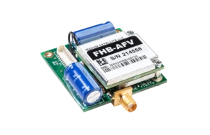
RockBLOCK 9603
RockBLOCK 9603 is targeted primarily at systems integrators and product developers where space inside your enclosure is at a premium. RockBLOCKs can send and receive short messages from anywhere on Earth with a view of the sky.
Supporting the Eldorado Space Program
In 2014, Paul McWhorter, a 17-year veteran of Sandia National Labs and founder of a Silicon Valley nanotechnology company, returned to his hometown of Eldorado, Texas, to start a new career as a high school teacher.
When not teaching math and engineering classes at Eldorado High School, Paul devotes time to lecturing on subjects ranging from how to become a successful engineer, programming with Arduino/Raspberry Pis, and learning 3D CAD. Paul uploads his lecture videos on his website and YouTube channel.
Much to everyone’s surprise, Paul also established the high school’s first space program. He oversees a four-year high school engineering program where younger students are encouraged to join the space program in their junior and senior years.

With his guidance, students design, build, and program instrumentation packages sent into the upper atmosphere via high-altitude balloons. He documents the missions in a dedicated YouTube channel.
The instrumentation packages, called Eagles, are sent to the edge of space and transmit back temperature, pressure, and GPS data, as well as live video. A 9-axis inertial measurement system also sends data on the Eagle’s orientation. In all, twenty different data channels are telemetered back to ‘Mission Control’ in the classroom. Some of the additional data channels include down range velocity, vertical ascent rate, latitude, longitude, elevation, system health, signal strength, downrange distance, heading, and trajectory.
A unique accomplishment of these student engineers is their development of an ability to stream live video from the edge of space back to the classroom. The students use standard 2.4 GHz Wi-Fi radios and reconfigure them to operate on the 2.39Ghz HAM microwave radio band. Each member of the program has a HAM radio license, so they can legally operate on this microwave band.
Since the instrument packages can reach altitudes over 115,000 feet and can travel 100 miles down range, maintaining a live video link is a formidable challenge. Technical and regulatory requirements limit the space-bound microwave radio to 1 watt transmit power. In order to communicate over these large distances at such a low power level, a high-gain antenna is required on the ground-based tracking system.
The challenge of using a high-gain antenna on the ground is that it must be pointed with precision at the space-bound instrument package. A pointing error of just a few degrees can lead to loss of signal. According to Mission Commander Jack Griffin: “The challenge becomes even more formidable since the instrument package can reach speeds of over 150mph, as the package ascends through the jet stream. Imagine trying to hit a target with one-degree precision that’s over 100 miles away, traveling at over 150mph.”
Griffin, who is a 17-year-old high school senior, continues: “We’re definitely solving real-world problems in this program. It’s more like working for a Silicon Valley start-up than being in a high school class.”
The ground-based tracking antenna is mounted on a Pelco Pan/Tilt platform. The position of this platform is controlled by relays in a closed-loop feedback system run on a Raspberry Pi microcontroller. The control system works as follows: A GPS on the space-bound instrument package measures the package’s latitude, longitude, and altitude. This data is then transmitted back to the ground- based tracking system. The system then takes these data points and applies the complex Haversine computation to calculate the necessary heading and elevation for the antenna to be precisely pointed to the instrument package. A feedback loop then moves the Pelco such that the antenna is precisely pointed at the target coordinates. In order to maintain the microwave video link, this feedback loop must constantly and quickly adjust the antenna position.
High school junior and Ground Tracking Specialist Benjamin McGee claims: “This is definitely a challenge and mission success depends on keeping the ground-based antenna pointed precisely at the package, no matter where or how fast it goes.”
The team is busy working on preparations for the launch of Eagle IX. Mission Commander Jack Griffin is confident that this will be the best launch ever. Griffin says: “We have our flight designed and expect to get our highest-quality images and most precise data to date, which we will live-stream on our YouTube channel so anyone on Earth can see it.”
The key element for this entire system to work is to have a reliable way to get the GPS data back from the space-bound instrument package to the ground-based tracking system.
Mission Specialist Christine Lindsey says: “Mission success depends on reliable transmission of GPS coordinates from the instrument package back to the ground, We’ve chosen the RockBLOCK modem and Iridium satellite network because it provides rock-solid connectivity. Initially we sent the GPS data coordinates over our microwave link, but if we lost connection, there was no way to regain it. With the RockBLOCK, we always know where the package is and how to point to it. With this system, we can maintain our microwave data link.”
This high-frequency radio beam has poor propagation, meaning it’s important to aim the antenna precisely at the Eagle. To achieve this, GPS data is transmitted via RockBLOCK to Ground Control’s servers. It’s then pushed via HTTP post to Paul’s own server which adjusts the high-gain antenna position accordingly, thus maintaining the video link.
Get in touch
Get in touch with us and find out if the RockBLOCK 9603 is the right device for your needs. Either complete our online form, or call us to be connected directly with one of our expert team. Call +44 (0) 1452 751940 (Europe, Asia, Africa, Oceania) or +1.805.783.4600 (North and South America).
With over 20 years experience in satellite tracking we have the knowledge and experience to ensure you are equipped with everything you need to make the right choice.