Topic: IoT & M2M
Satellite Data Delivery for Any Logger: RockREMOTE Mini’s SMTP Server
From the Solutions Team
This article was written by Michael Mitrev, Solutions Architect in Ground Control’s pre-sales Solutions team. Michael has been closely involved in the development and testing of the RockREMOTE Mini and RockBLOCK RTU, with a particular focus on data logger integrations. Here, he shares practical implementation guidance, configuration examples and lessons learned from hands-on testing and customer deployments.
If your device can send an email, it can send data over Iridium. No custom protocol, no firmware changes, no serial AT commands. Just point it at the Mini.
Quick Links: NRG SymphoniePRO | Campbell Scientific Loggers | Axis Communications Cameras
RockREMOTE Mini SMTP Server
RockREMOTE Mini runs a local SMTP server on its Ethernet interface, accessible at 192.168.250.1 port 25 by default. Any device on the Mini’s local network can connect to it and send a standard SMTP message with a file attachment. That’s it, as far as your device is concerned. The Mini takes care of everything that happens next.
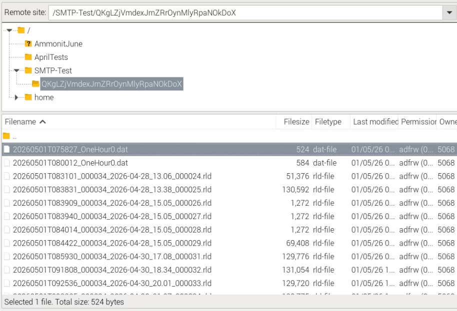
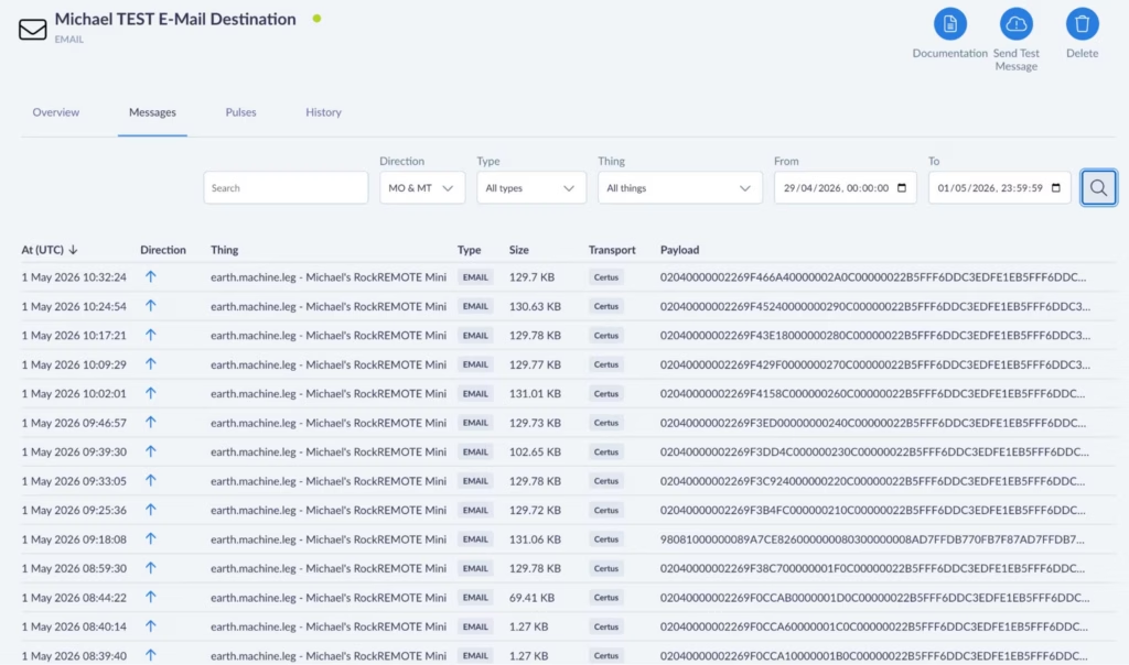
Example screenshot showing an FTP server destination with NRG RLD files and Campbell DAT filesInternally, the Mini compresses the attachment and transmits it as one or more IMT (Iridium Message Transport) messages over the Iridium Certus 100 network to Cloudloop Data. Cloudloop decompresses it and delivers it to your configured destination, which could be an inbox, a webhook, FTP server, an S3 bucket, or any other destination Cloudloop Data supports. Your device never needs to know any of this is happening.
A few key constraints worth knowing upfront:
- Max attachment size: 165 KB
- Recipients: one To field, up to two CC fields
- Authentication: none required (and none currently supported – leave username/password blank) with the exception of NRG Loggers
- Port: 25 only
The SMTP server must be enabled in the Mini’s user configuration file, and you need an Email Destination set up in Cloudloop Data with your Mini in the relevant device group (select Payload, Plaintext, and Assume Destination from Source).
What’s the Point?
Using SMTP isn’t really about sending Email. While it absolutely can be used to send email end-to-end, I don’t really see it as an email feature. I see it as a universal file transport mechanism.
If you’ve worked with SBD or IMT products before, you’ll know that you’re normally just sending the raw data. If that data happens to be a file, it’s then up to your individual applications on both the sending and receiving end to preserve or reconstruct the filename, extension and format, as well as implement whatever message handling, retries and timeouts needed to get it there in the first place.
With the Mini’s SMTP server, we’ve already solved that. Your device simply sends what it thinks is a normal email with an attachment, and at the other end you receive the original file with its filename, extension and format intact.
It’s essentially a one time setup on your side that results in complete files arriving at their destination without having to write any file reconstruction logic – we’ve taken care of that and the internal message handling process for an almost-guaranteed file receipt.
Why IMT?
When your attachment lands at the Mini’s SMTP server, it doesn’t go out over IP; it goes out over IMT. That distinction matters for running costs.
IMT is Iridium’s message-based transport protocol. Unlike IP, it carries no per-packet header overhead, and its minimum billable unit is 25 bytes (1 byte increments thereafter) rather than IP’s 1 KB (100 byte increments thereafter). For periodic data delivery – a file every hour, or once a day – this makes a meaningful difference to your airtime bill over a long campaign. The Mini also compresses attachments before sending, which reduces the byte count further.
For most monitoring deployments, SMTP over IMT is the right choice for scheduled data delivery: low cost, reliable, and completely hands off once configured.
IP and IMT Simultaneously
The Mini runs IP and IMT at the same time. This is worth emphasising, because it means your scheduled data delivery over IMT doesn’t stop you from also using the IP link for other purposes.
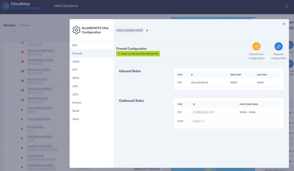
The Mini’s public IP (assigned and managed by Ground Control) can be used with port forwarding rules to provide direct access to any device on the Mini’s local network – your logger, your sensor hub, a web interface. These rules are configured either in the Mini’s user configuration file, pushed over the air via Cloudloop Device Manager, or set up via the RockCONNECT IoT BLE app.
Cloudloop NOC also offers whitelisting of public IP addresses that are allowed to reach your Public IP, it’s a block-all by default.
A typical inbound rule – forwarding connections on a WAN port through to a specific device (NRG Logger in this case) on the LAN:
And if the logger needs to initiate outbound connections to a specific server (NRG’s in this case):
The Mini’s IP link runs at 22 Kbps Transmit and 88 Kbps Receive – more than enough for remote access, configuration changes, and live data viewing. IMT handles the low cost scheduled delivery; IP handles everything interactive. You get both, from the same device, on the same Iridium link and with five or more devices you can benefit from a shared data pool.
NRG SymphoniePRO + iPackACCESS
NRG Systems’ SymphoniePRO is one of the most widely deployed meteorological data loggers in the wind energy industry, used globally for resource assessment and power performance campaigns. It has had SMTP data delivery built in from the start, making it a natural fit for the Mini’s SMTP server.

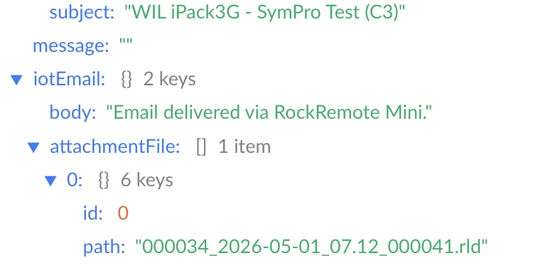
The iPackACCESS is the communications and power module that attaches to the back of the SymphoniePRO. It provides the logger with an Ethernet interface and handles all outbound communications: SMTP delivery of .RLD data files on a scheduled basis, and MetLink connections for interactive remote access via the SymphoniePRO Desktop Application.
Integrating with the RockREMOTE Mini is straightforward:
- Connect the iPackACCESS’s Ethernet port to the Mini’s LAN
- In SymphoniePRO Desktop Application, assign the iPackACCESS a static IP in the Mini’s subnet (e.g. 192.168.250.90)
- Set the SMTP server to 192.168.250.1, port 25
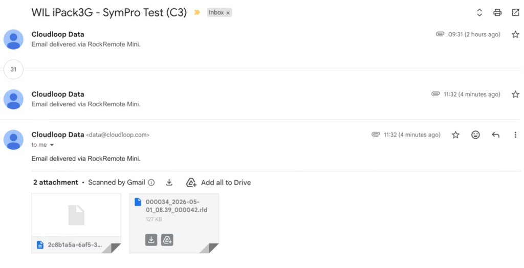
- The logger delivers .RLD files to Cloudloop Data on its configured schedule, which can then be accessed via NRG Cloud or pulled directly into SymphoniePRO Desktop Application as normal.
For MetLink remote access – live data, configuration changes, manual data pulls – configure an inbound port forwarding rule in the Mini pointing to the iPackACCESS’s LAN IP. If using logger-initiated MetLink, add a corresponding outbound rule allowing the logger to reach your server. Ground Control assigns a static public IP to your Mini; SymphoniePRO Desktop Application connects to that IP on the forwarded port and communicates with the iPackACCESS exactly as if it were going over terrestrial WAN networks.
NRG Systems are trusted partners of Ground Control. They worked closely with us during development of the Mini’s SMTP functionality to ensure it integrates correctly with the SymphoniePRO and iPackACCESS system, so if you’re an NRG customer looking to add Iridium satellite telemetry, they’re fully across this solution and can handle the setup end to end. We’d strongly recommend reaching out to them directly!
Campbell Scientific Loggers
Campbell loggers – CR1000, CR6, CR300, CR800, CR1000X and others – have had the EmailSend function in CRBasic for many years. It can stream data table records as file attachments on a scheduled basis, over SMTP.

Getting a Campbell logger talking to the Mini requires minimal changes to an existing program: set the SMTP server address to 192.168.250.1:25, and leave the username and password fields as empty strings. Your data tables, scan intervals, and field processing don’t need to change at all – just add the SMTP function and the only prerequisite is to have the logger connected via Ethernet to the RockREMOTE Mini and a static or DHCP IP set in the same subnet.
EmailSend with FileOption 8 produces TOA5-format output: headers, timestamps, and record numbers in the standard Campbell ASCII format, compatible with LoggerNet, PC400, and most downstream tools. The time-window arguments let you stream the last hour of records, the last day, or all records since the last reboot.
For remote access, the same port forwarding approach applies. IP at 88 Kbps Receive and 22 Kbps Transmit is more than comfortable for LoggerNet connections – editing programs, pushing updates, pulling live data or on demand table records.
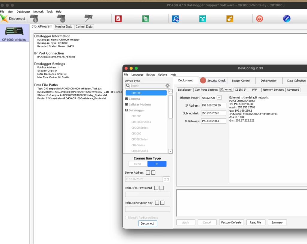
A CRBasic example is available below – I wrote and applied my entire test SMTP program over the Satellite Network! There’s also a more detailed IMT and IP Campbell-specific walkthrough in our previous post.
A Non-Logger! AXIS Cameras
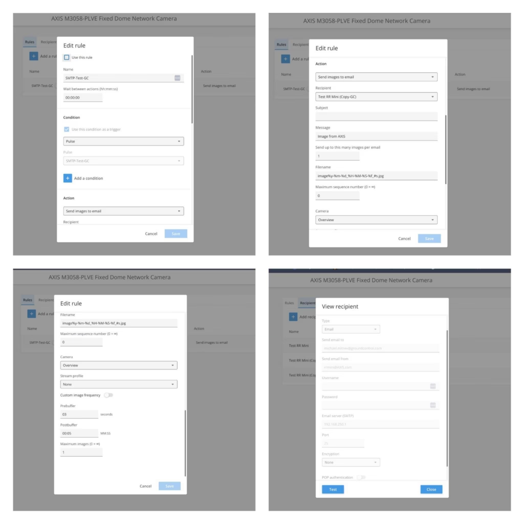
Even though they’re not a logger, AXIS cameras are usually installed next to loggers due security reasons, they also support event-based email delivery with image attachments, which makes integration with the RockREMOTE Mini straightforward. Configure the camera to send images via SMTP to 192.168.250.1:25 with no authentication, and assign it an IP on the Mini’s LAN.

Even though they’re not a logger, AXIS cameras are usually installed next to loggers due security reasons, they also support event-based email delivery with image attachments, which makes integration with the RockREMOTE Mini straightforward. Configure the camera to send images via SMTP to 192.168.250.1:25 with no authentication, and assign it an IP on the Mini’s LAN.
On trigger (motion, schedule, I/O), the camera sends a JPEG image as an email attachment. The Mini receives it, compresses it, and delivers it over IMT to Cloudloop Data, where it is forwarded to your configured destination.
For best results, keep to 1 image per event and avoid high trigger frequency to maintain efficient IMT usage. At the same time, IP can be utilised for live streams if required.
Any Device That Can Send SMTP
The pattern here is simple enough that it applies far beyond branded data loggers. If a device can send a standard SMTP message with a file attachment, it can deliver data over Iridium via the Mini.
That includes Linux systems using mutt or swaks; embedded boards with a TCP/IP stack and an SMTP client library; industrial instruments, PLCs, and weather stations with a built-in email function; or any custom application – a Python script, a shell cron job… Any SMTP client really!
Further Reading
- RockREMOTE Mini overview
- Antenna Mounting and Sky View
- Mini SMTP documentation
- Integrating RockREMOTE Mini with the CR1000
- Cloudloop Data documentation
Discuss Your Integration
Have a specific integration in mind? Our Solutions team works with developers every day to help connect existing equipment over satellite.
If you have a technical question, get in touch via the form, or by emailing hello@groundcontrol.com.
Why Resilient Connectivity Matters in Offshore USV Operations
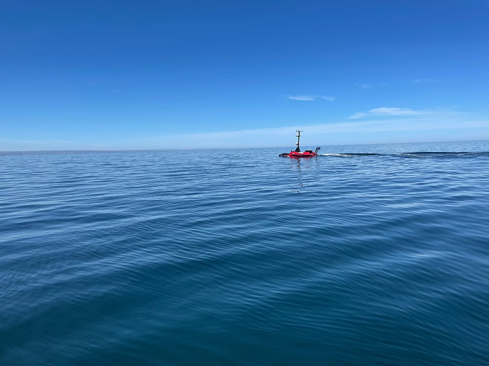
The USV market is growing quickly. Allied Market Research says it’s projected to reach $2.7 billion by 2032, growing at an 11.5% CAGR. MarketsandMarkets points in the same direction, forecasting growth from $0.82 billion in 2025 to $1.59 billion by 2030 at a 14.1% CAGR. Behind those forecasts is a simple idea: operators want to do more offshore, for longer, with less risk to crew and a better cost profile.
As missions become longer and more complex, connectivity becomes a bigger part of the operating model. Operators need to know they can maintain oversight of the mission, receive alerts when conditions change, and keep essential data flowing even when the primary link is under pressure.
That matters because offshore environments are rarely forgiving. Sea state affects antenna performance, weather can affect signal quality, and coverage isn’t always consistent across an entire mission. Communications systems need to be designed around those realities, rather than around best case assumptions.
Why connectivity has such a direct impact on the business case
Connectivity affects both operational performance and commercial performance. If a vessel loses its main link but can continue operating safely while still sending health data, position reports, and exception based alerts, the mission may continue with only limited disruption. If the vessel goes dark in a way that removes visibility and confidence, the cost picture changes much more quickly.
Published data on the cost of recovering a USV is limited, but offshore operating cost studies show the broader dynamic clearly. Once a crewed vessel, personnel, mobilisation, and weather related delays are back in the loop, costs rise fast. In one NREL offshore operations model, a relatively modest crew transfer vessel scenario was estimated at around $4,100 per day. That’s not a dedicated USV recovery figure, but it does illustrate why operators want to avoid reintroducing crewed intervention unless they absolutely have to.
That’s why resilient connectivity matters commercially as well as operationally. It helps preserve confidence in the vessel’s status, the payload’s output, and the economics that justified using a USV in the first place.
What operators are actually evaluating
One of the clearest signals in this market comes from the kinds of conversations already happening around offshore connectivity. In our role as a remote connectivity specialist, we receive inquiries from USV operators and manufacturers who are actively evaluating how to keep vessels safe, visible, and manageable when the primary link is under pressure.
Those discussions are often less about maximum throughput in the abstract and more about what needs to keep working when conditions aren’t ideal. The priorities tend to be safety override, basic telemetry, vessel tracking, low rate command traffic, and a backup path that can take over if the main link drops.
We also see strong interest in backup satellite communications and last resort systems that can preserve continuity when a richer link is unavailable. That suggests the market is moving beyond a simple question of whether a USV can connect offshore. The more practical question is which functions need to be protected, and which link is best suited to carrying them.
Why primary and backup links should be treated differently
A useful way to think about offshore USV connectivity is to separate the role of the primary link from the role of the backup. The primary link supports the fuller operating picture. Depending on the mission, that may mean higher rate telemetry, software updates, larger payload files, imagery, video, or more responsive command and control. High bandwidth satellite services have expanded what is possible here and have made remote offshore operations much more practical than they once were.
The backup link has a narrower role, but it’s no less important. It exists to preserve essential functions when the primary link is constrained or unavailable. In practice, that often means vessel health, alarms, mission status, low rate command traffic, and, in some cases, compressed imagery or short bursts of additional data. It doesn’t need to recreate the entire primary link experience; it needs to provide enough continuity for the vessel to remain safe, visible, and manageable until the richer link is available again.
That distinction is reflected in the way these requirements are typically framed. The fallback path is often defined in terms such as safety override, telemetry, tracking, or a “Hail Mary” communications layer.
That tends to lead to better architecture decisions because it matches the way communications are actually used at sea. Not every function needs the richest link, but some do need to keep working almost regardless of conditions. Onboard autonomy has a role here, but operators still need enough visibility and control to stay confident in what’s happening offshore.
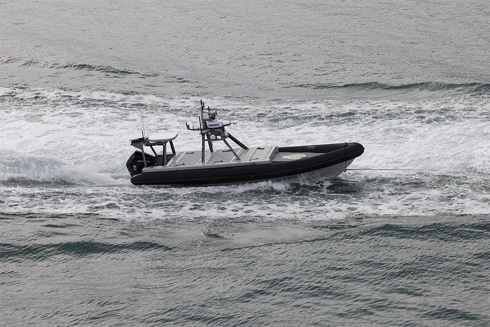
Why a single broadband satellite link leaves gaps offshore
Broadband satellite has changed offshore connectivity for the better; it supports a much richer operating model, and it can make remote operations far more practical for larger USVs. But relying on one broadband service on its own still creates a dependency on a single communications path.
That means one antenna setup, one service profile, one network architecture, and one main route back to shore. If that route is affected by weather, vessel motion, local obstructions, hardware issues, or service constraints, the mission can lose the level of connectivity on which it was relying. Starlink itself notes that significant weather can degrade service, that moderate to heavy rain, snow, and hail can cause momentary dropouts, and that storms near a local ground station can also affect performance. Its maritime service information also says that once Priority Data is exhausted, users fall back to rates of up to 1 Mbps down and 0.5 Mbps up.
That risk is one reason many operators are actively evaluating layered satcoms rather than a single broadband path. In our conversations with USV manufacturers and operators, a recurring theme is the need for backup communications that can preserve control, visibility, and essential status data if the primary service drops, even briefly. A strong primary link is valuable, but resilience usually depends on having a second path for the functions that matter most.
Why layered satcoms make sense for offshore USVs
This is where layered satellite communications start to make sense. A primary link supports the richer operating picture when conditions allow. A secondary link helps preserve the essentials if the main path is constrained. For many offshore USV applications, Iridium Certus 100 is a good example of what that secondary communications layer can look like. It’s well suited to telemetry, alerts, command traffic, and other continuity functions that don’t need broadband throughput.
It also aligns with the way missions behave in practice. Data needs aren’t constant across a deployment. There will be times when high throughput is useful and times when the priority is to maintain visibility of vessel health, mission progress, and any exceptions that require attention. A backup link is well suited to those moments, particularly when the vessel can keep operating in a controlled way while communications are degraded.
That matches what we see in the market, where operators are increasingly focused on which functions need to be protected if the main path is interrupted, rather than on preserving full bandwidth at all times.
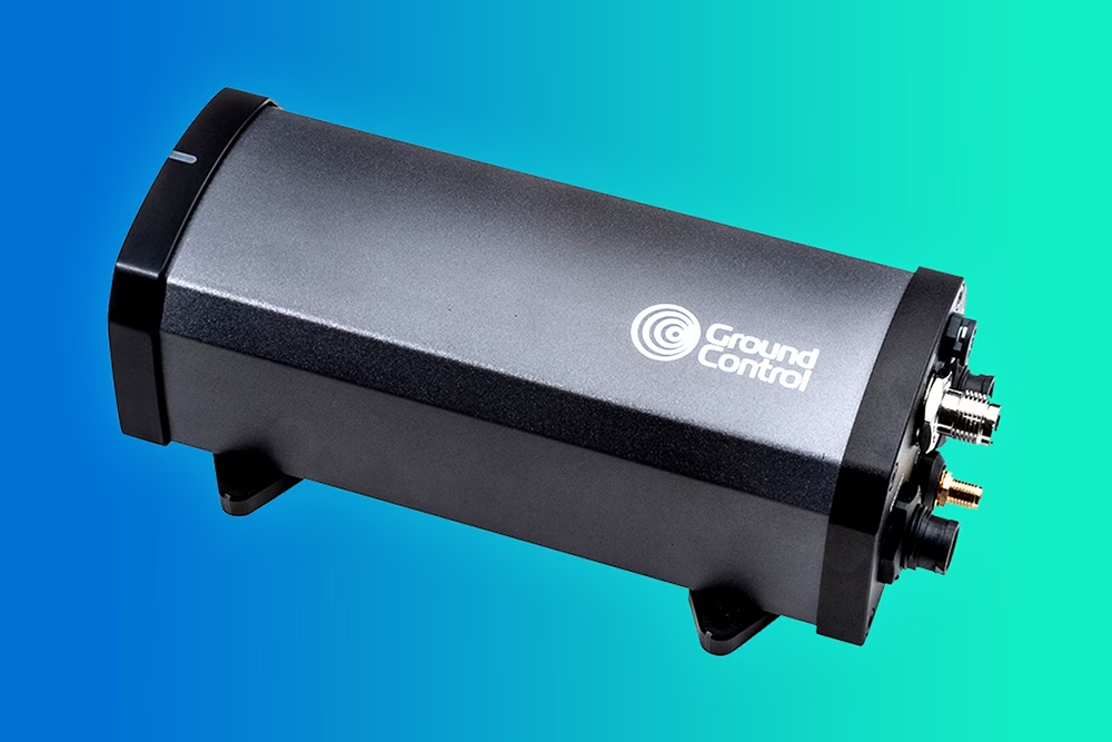
What operators should be asking as the market grows
As the USV market expands, connectivity deserves to be discussed with the same realism that is now routinely applied to autonomy, payload design, and endurance. What happens when the primary link is degraded? Which functions are preserved? What information still gets through? Can the vessel continue operating safely? Can the operator remain confident in the mission without immediately considering recovery?
Those questions matter because offshore operations are shaped by constraints, not just capabilities. A communications setup that works well in a demo or a short mission close to shore may not be enough for a longer deployment in more variable conditions. By contrast, a layered approach that combines a richer primary link with a lower bandwidth backup can give operators a more dependable path through the realities of offshore operations.
That’s why resilient connectivity has become such an important consideration in USV design and deployment. It supports visibility, continuity, and operational confidence, and it helps ensure that a temporary link issue doesn’t become a much more expensive problem.
Need help with offshore USV connectivity?
If you’re looking at offshore USV connectivity and weighing up primary and backup options, it’s worth having that conversation early. The right architecture depends on the mission, the data you need to move, and the functions that have to keep working if the main link is interrupted.
At Ground Control, we work with operators and manufacturers on exactly these kinds of remote connectivity challenges. If you’d like to talk through a specific use case, get in touch with us either by completing the form, or emailing hello@groundcontrol.com. We’ll reply within one working day.
Remote Conservation at Wildfire Risk: Monitoring and Alerting with Satellite IoT
For teams managing remote conservation areas, wildfire risk is becoming harder to predict and harder to plan for, even in regions that have not historically been considered fire prone. Rising temperatures and longer dry periods are changing how fire behaves across forests, reserves, and protected land. One recent study found that 83.9% of wildfire-vulnerable species are now exposed to increased fire risk, with fire seasons projected to more than double in some regions. This isn’t limited to traditionally fire-prone zones. Fire seasons are lengthening, and fire behaviour is becoming less predictable and harder to contain.
You may already be seeing the signs: vegetation staying dry for longer, water sources becoming less reliable, and more ignition points across a wider area. For smaller teams covering large territories, this shifts wildfire from a seasonal concern to an ongoing operational risk.
Why remote sites are exposed
Remote conservation areas come with structural challenges that make wildfire response harder. Teams often work across large, varied terrain with limited visibility, minimal infrastructure, and inconsistent or absent cellular coverage. Ranger teams are small, but the areas they cover are not.
When a fire starts, response depends heavily on what you can detect and communicate locally. In Madagascar, one protected reserve lost around a third of its forest in a single year due to wildfire pressure linked to rising temperatures and prolonged dry conditions. Events like this highlight how quickly impact scales when detection or response is delayed.
Distance from emergency services also increases pressure on conservation teams, while budget constraints shape what can realistically be deployed. And when habitats support endangered species, even a single event can cause long-term ecological damage.

What monitoring looks like today
Wildfire monitoring is typically shaped by scale and budget. In practice, teams may rely on ranger patrols and visual observation, weather tracking such as temperature, wind, and humidity, external satellite data sources, camera systems, or WAN sensor deployments.
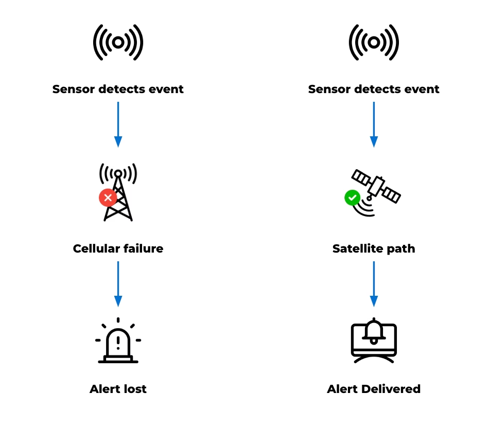
These tools are valuable. They provide signals, support situational awareness, and in some cases trigger real time responses. However, while the capability to monitor exists, the limitations of existing approaches are largely practical. Detection may depend on chance observation and can come too late, while reliance on cellular communication can fail under the stress of an unanticipated emergency that disrupts the very channels needed for response.
Even when sensors are deployed, reliably transmitting alerts can be difficult. Data may be captured but not delivered effectively, creating a gap between detection and awareness. Constraints like these become more visible as wildfire risk increases.
Why time is of the essence
Delays in detecting early-stage fires reduce the available window for intervention. In fast-moving conditions, even short delays can significantly increase the scale of an incident. At the same time, teams may be distributed across the landscape, and lone workers need reliable communication for both safety and coordination.
The 2024 Jasper National Park wildfire shows how quickly situations can escalate, even in well-managed environments. The event led to around 25,000 evacuations and the loss of hundreds of structures. In more remote settings, with fewer resources, the margin for delay is even smaller.
Detection works. Delivery is the problem
Deploying sensors to monitor temperature, humidity, and smoke across high risk areas can provide meaningful early signals from systems that run for long periods on minimal power.
The FireFly project in Northern Thailand is a strong example. Distributed sensor nodes monitored forest conditions and identified early fire risk, with UAVs used to confirm ignition points. The system was designed specifically for remote, low infrastructure environments with cost in mind. But field observations highlighted a recurring issue: antenna placement and enclosure design affected system reliability, while dense vegetation and uneven terrain disrupted connectivity. Environmental conditions directly influenced whether data could leave the site. In other words, detection worked, but alert delivery didn’t always follow.
The same pattern appears in field-based wildfire and peatland monitoring projects more broadly. Sensors can detect early stage fire risk, land degradation, or changing environmental conditions, but the value of those systems depends on whether data can leave the site quickly and reliably. Studies of IoT wildfire detection systems highlight communication reliability, limited cellular coverage, packet loss, latency, and energy consumption as practical deployment challenges in remote environments. The communication channel, or “last mile” connection, is therefore critical to whether early detection becomes timely awareness.
Solving the last mile with Satellite IoT
In remote conservation areas, terrain, vegetation, and distance from infrastructure all affect signal performance. Systems that depend on terrestrial networks introduce gaps and points of failure. Satellite IoT removes that dependency.
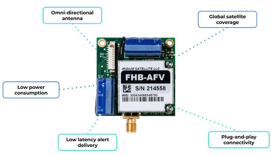
By integrating a compact modem such as RockBLOCK 9603, a sensor monitoring system can send data over the Iridium satellite network with no reliance on local infrastructure. That creates a direct path from your sensor to you, without relying on local coverage.
In practice, the workflow is simple:
- Sensors monitor defined environmental thresholds
- Local logic determines when conditions require attention
- A short alert message is generated
- That message is transmitted via satellite to your team.
Messages remain small, and transmission can be event driven, supporting low power operation and long deployment lifetimes. For conservation teams, this enables a focused deployment model: a limited number of sensors placed in high risk areas, with a communication path that remains consistently available.
When a fire is detected, the system alert is delivered, reliably, and in time to act.
When you need more field capability
For some deployments, a compact satellite modem may be enough to connect an existing sensor system. For others, the monitoring setup needs to handle multiple sensor inputs, apply logic locally, and decide when an alert should be sent.
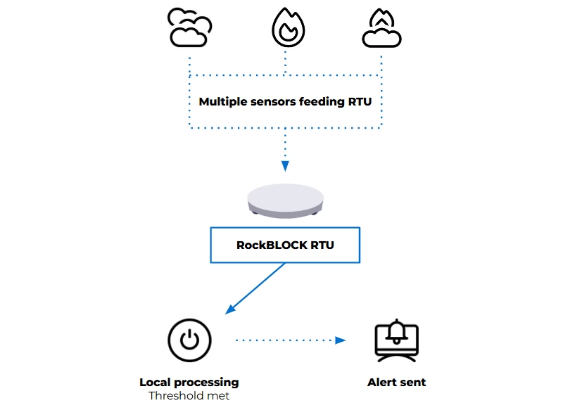
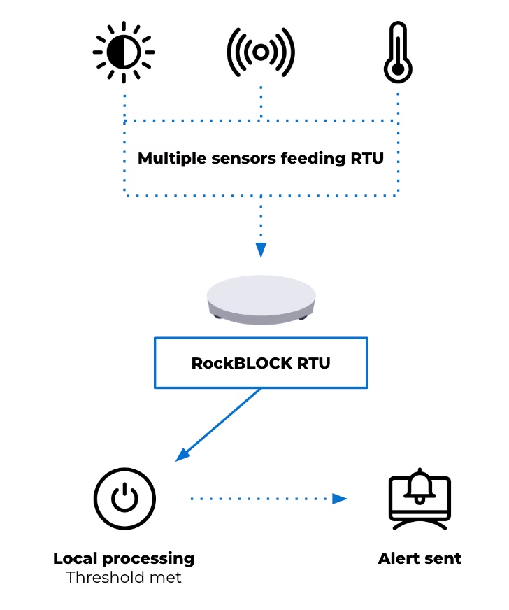
That’s where a device such as RockBLOCK RTU can be useful. It aggregates sensor inputs from a range of sources and applies threshold logic in the field. When defined conditions are met, it generates alerts and transmits telemetry via its satellite connection.
This approach reduces dependency on continuous connectivity and avoids the need to send raw data elsewhere for processing. Decisions are made where the data is generated, according to the conditions being monitored. Reducing unnecessary data transmission also helps keep satellite costs to a minimum.
In practice, that gives you:
- One unit integrating multiple sensors
- Configurable thresholds based on your environment
- Event-based alerting instead of continuous transmission
- Context included with each alert.
The right approach depends on the scale of the site, the number of sensors required, and how much processing needs to happen in the field.
Designing for increased wildfire risk
Effective wildfire monitoring systems prioritize early detection and dependable alert delivery. They need to operate with limited power, minimal infrastructure, and changing environmental conditions, while remaining simple enough to deploy and maintain and reliable enough to trust when something happens.
Recent events reinforce the need for this approach. Reliability, simplicity, and clear information delivered to the right people at the right time can protect lives and support more effective response.
Facing a remote monitoring or alerting challenge?
If your team needs to detect environmental risk, transmit alerts from areas without reliable cellular coverage, or keep remote systems connected, we can help you explore the right satellite IoT approach.
Complete the form, or email hello@groundcontrol.com to discuss your use case with our team – we’ll reply within one working day.
From Alerts to AI: Satellite IoT in Landslide and Earthquake Monitoring Systems
April 2026’s reports of seismic activity and tsunami warnings in Japan have again highlighted how critical early warning systems are. Events like these reinforce a consistent reality: detection is only part of the system. The ability to communicate alerts quickly and reliably remains central to reducing impact.
As landslide, earthquake and tsunami monitoring systems evolve, this communications challenge is becoming more complex. Monitoring is moving beyond single parameter approaches toward multi-sensor systems that integrate different data types to improve situational awareness and reduce false positives. At the same time, research institutions are applying machine learning and deep learning techniques to identify patterns that may be difficult to detect through rule-based models alone.
These developments increase system capability, but they also change system requirements. More sensors generate more data. AI-driven approaches require datasets that are larger, more continuous and better contextualized. As a result, monitoring system design now has to account not only for detection, but also for power, data volume, transmission frequency, and the role of processing at the edge.
Detection is only useful if the alert gets through
Detection capability has improved significantly, and monitoring systems can often identify early signs of instability. But detection only matters if alerts reach the right people in time. That remains difficult in remote terrain. Monitoring sites are often located where infrastructure is limited, ground conditions are unstable, and access is restricted. Power depends on what the natural landscape allows, while cellular networks may be unavailable, unreliable, or vulnerable during an event.
As a result, a system can continue collecting data even when its communications path fails. This creates a gap between detection and action, reducing the value of the system no matter how capable the sensing layer is. International frameworks on early warning systems highlight that coverage is improving globally, but reliability and last-mile delivery remain key challenges.
Satellite connectivity can help close that gap. Because it does not rely on local infrastructure, it provides an independent communications path for remote or vulnerable locations. Ground Control’s earlier work in tsunami early warning systems in Thailand demonstrates how satellite connectivity can support resilience and last-mile data delivery, helping ensure that critical alerts can reach emergency response systems when local infrastructure is limited or unavailable.
Natural hazard monitoring is becoming more data intensive
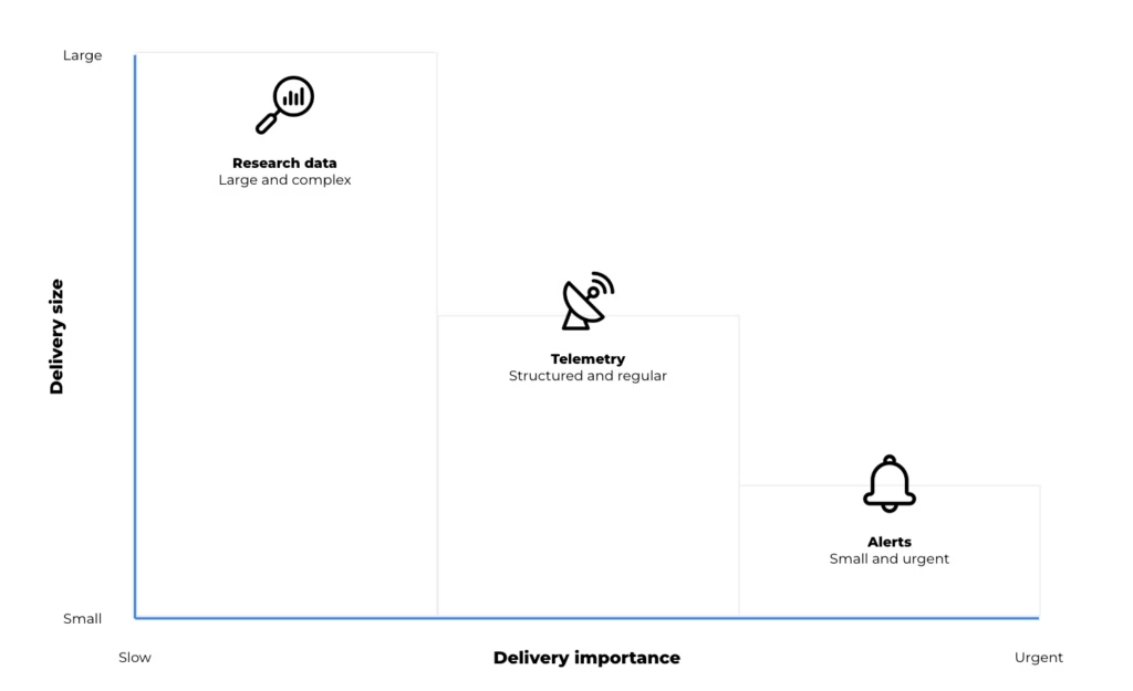
As scientific research continues to evolve, natural hazard monitoring systems can generate a broad range of data. Traditional threshold-based systems typically produce discrete, event driven messages. Multi sensor deployments and research programs, by contrast, may generate continuous and contextual datasets that support analysis, model development, and validation. Within a single monitoring system, data may include:
- Time critical alerts
- Ongoing telemetry
- Device and system health data
- Larger datasets used for analysis and research
- Photographic, mapping, audio, or video data.
Modern systems may combine LoRaWAN sensor networks, remote sensing methods such as radar, terrestrial and non-terrestrial communications, and both edge and cloud processing. Satellite devices are introduced into these systems to address coverage gaps, provide an independent communication path, or support resilience where terrestrial networks are limited.The key point is that not all data behaves in the same way. A short emergency alert has very different requirements from periodic telemetry or a large dataset used for research. In practice, satellite IoT devices can support different roles depending on the size, urgency and value of the data being transmitted.
Three types of data, three connectivity roles
In earthquake, landslide and tsunami monitoring, the connectivity question encompasses what kind of data needs to move, how urgently it needs to move, and how much processing should happen before it leaves the site. Broadly, data requirements fall into three categories:
| Alerts | Telemetry | Research and AI Data | |
|---|---|---|---|
| Typical Behavior | Small, urgent, event driven | Regular, structured, operational | Larger, richer, less time critical |
| Main Requirement | Must get through | Efficient visibility over time | Filtering, storage and selective |
| Satellite IoT Role | Resilient short message transmission | Periodic monitoring and backhaul | Edge processing and higher capacity |
1. Time critical alerts: small messages, high consequence
For alert generation, the desired output may be a critical message triggered by defined thresholds or rules. When conditions are met, an alert can be generated at the device level and transmitted as a short message. This reporting by exception approach reduces dependence on continuous connectivity and helps keep satellite airtime costs to a minimum. Alerts are triggered by local conditions and transmitted when a predefined perimeter is breached.
This isn’t to suggest that hazard monitoring is simple. Rather, some parts of the system still depend on very small, high priority messages: a threshold has been crossed, a device has changed state, or an alarm needs to be raised.
Devices such as RockBLOCK RTU are designed for this type of integration and event driven monitoring. Supporting multiple sensor inputs and enabling local data batching at the edge, the RTU allows data output to remain minimal in size but critical in importance.
This reflects the same principle seen in the tsunami early warning system mentioned earlier, where the priority is ensuring that critical signals can be generated and transmitted under constrained conditions. The RTU also offers sensing, data logging and action on basic threshold triggers. It’s not designed for high level data processing, but it can play an important role in raising an alarm, warning a community, and ensuring that the message gets through.
2. Telemetry: maintaining visibility between events
Alerting is only one layer of a monitoring system. Beyond emergency messages, earthquake and landslide monitoring systems also require ongoing visibility into environmental conditions and system status. Telemetry requirements may include periodic sensor readings, device diagnostics, system health information, and environmental trends over time. This data supports the interpretation of conditions leading up to and following an event. It can also be used to validate system performance and support operational decision making.
Here, architectural decisions often depend on project cost, power budget and the frequency of transmission. Compared with short alert messages, telemetry may require greater data capacity and more regular communication. It remains structured and predictable, but introduces additional considerations around bandwidth and power usage.
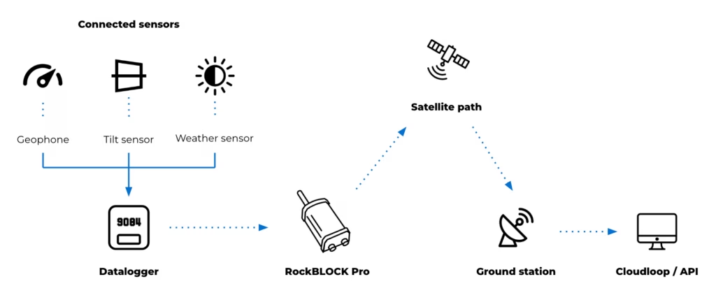
For these purposes, devices operating over services such as Iridium Messaging Transport (IMT) may support this type of data flow. RockBLOCK Pro delivers faster throughput and enables larger payloads than SBD, supporting aggregated sensor data, images and audio clips up to 100kB. This provides more flexible data transmission patterns compared to low bandwidth messaging.
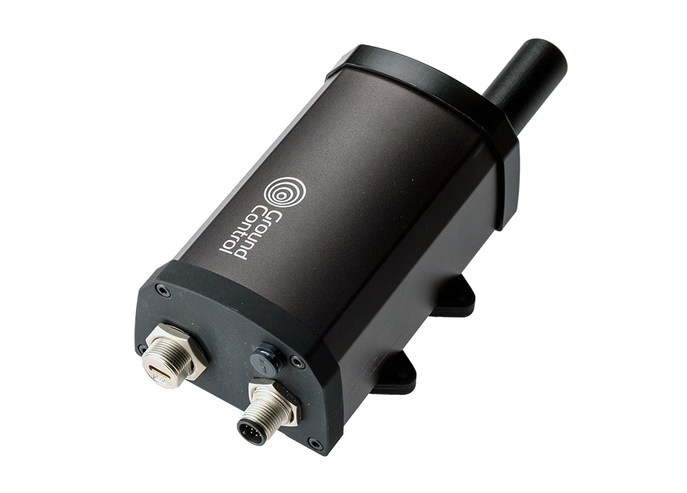
As an IP66 rated terminal, RockBLOCK Pro has a rugged design with a built in Iridium Certus antenna. Its combination of GNSS and serial interfaces (such as RS232/RS485) allows it to integrate with external systems or data sources, acting as a communications layer for structured telemetry and providing a means to transmit aggregated or processed seismology and landslide data. This may include:
- Ground movement sensors such as geophones and accelerometers
- Tilt and deformation sensors for slope and structural monitoring
- Pressure and moisture sensors for groundwater and subsurface conditions
- Threshold-based triggers such as seismic switches for alert activation
- Environmental sensors including rainfall and wind
- Serial connected instruments using RS485 or RS232
- USB field access for configuration, data retrieval and maintenance.
The introduction of RockBLOCK Pro for backhaul or resilience provides additional monitoring capability and a significant increase in capacity to support a wider remote natural hazard monitoring system.
3. Research and AI workloads: when raw data is too large to send continuously
As monitoring systems expand to support research and model development, data requirements extend beyond alerts and telemetry. These datasets may include high resolution sensor data over extended periods, multi sensor correlations across locations, and inputs used for training and validating analytical models. This type of data is higher in volume and less time sensitive, but still requires a reliable path from remote environments.
Systems often store or buffer data locally and transmit it based on available bandwidth, power and connectivity. This may involve scheduled transfers, event-based uploads, or selective transmission of processed data. Devices such as RockREMOTE Rugged support this role by combining higher throughput connectivity with embedded compute capability. They act as an interface between field deployments and cloud-based systems, enabling data handling, filtering and integration with external platforms.
At this point, the device’s role isn’t limited to communication; it becomes part of the data management architecture. High frequency sensing, particularly in seismic monitoring, can generate more data than can be transmitted continuously over constrained links. Local processing allows this data to be reduced before transmission. Tasks such as filtering, segmentation and feature extraction can be applied at the point of collection, allowing derived parameters to be transmitted in place of raw data.
This preserves the characteristics needed for analysis while maintaining manageable data volumes. Edge computing can also support lightweight analytical models at the edge, depending on the application deployed.
These models, typically trained on historical datasets, can be applied to live data streams to identify signals of interest. This may include distinguishing between background activity and patterns associated with instability or early seismic events. In these scenarios, transmission is based on relevance rather than volume. Data is prioritized according to its analytical value, rather than transmitted continuously.
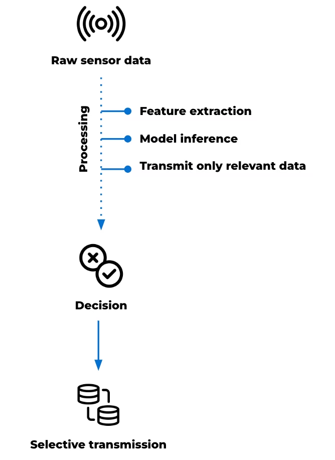
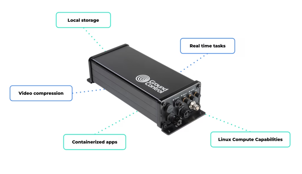
RockREMOTE Rugged’s Linux-based environment supports custom applications, enabling user-defined data processing and integration and allowing custom processing pipelines or models to be deployed at the edge. Local storage enables data retention where continuous transmission is not practical, while connectivity over Iridium Certus 100 and cellular networks provides a path for data to move to cloud environments when required.
This supports a range of system behaviors, including:
- High frequency data capture with selective transmission
- Local feature extraction to reduce bandwidth requirements
- Model inference at the edge to support early interpretation
- Buffered storage for later retrieval or batch upload
- Video compression before transmission
- Running real time tasks such as filtering, segmentation, or frequency-domain analysis
- Saving high resolution data locally
- Transmitting exception summaries via satellite.
In earthquake and landslide monitoring, the value of this compute power is in its ability to manage complex data flows locally, reduce unnecessary transmission, and support more autonomous system behaviour through locally defined logic or processing in remote environments.
Satellite IoT as part of the monitoring infrastructure
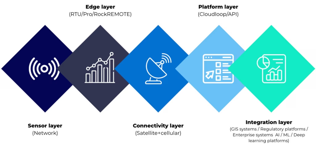
The evolution of landslide and earthquake monitoring systems is shaped by two parallel developments. The range of observable data is increasing through multi-sensor integration, remote sensing and advanced analysis. At the same time, environmental and operational constraints remain consistent. Monitoring sites are often remote, power limited and difficult to access. Communications infrastructure may be unavailable, unreliable or exposed to the same hazards the system is designed to monitor.
Within this context, connectivity supports the movement of different types of data, from time critical alerts to larger datasets used for analysis. Satellite enabled devices extend coverage and enable communication where other infrastructure is limited. Different device types support different roles within the system. Some are suited to edge-based alert generation. Others support structured telemetry and system visibility. Higher capacity devices with embedded compute power can help process, prioritize and transmit larger datasets for research and AI-assisted monitoring.
The most effective system design starts with the data: its urgency, size, frequency and operational value. From there, satellite IoT can be used as a resilient layer within a wider monitoring architecture.
Building the connectivity layer for modern monitoring systems
Whether you’re building threshold based alerts, expanding telemetry, or exploring edge processing for AI driven monitoring, the challenge is the same: getting the right data through, at the right time, under real world constraints.
We work with system integrators, scientists, and engineers, to design connectivity architectures that balance power, cost, data volume, and resilience across satellite and hybrid networks.
Complete the form or email hello@groundcontrol.com, and we’ll be in touch within one working day.
How Satellite IoT Can Underpin Confidence in Remote Water Systems Monitoring
Water quality monitoring no longer sits at the edge of operational strategy. It’s at the center of regulatory exposure, public reporting, and engineering accountability.
Designing or managing remote water quality monitoring systems lays the foundation for data continuity, defensible timestamps, and structured reporting outputs that withstand regulatory scrutiny. Across the UK, the United States, and other regulated markets, compliance expectations are tightening. Monitoring systems must now deliver continuous data, auditable records, and structured exports suitable for regulator portals and public dashboards.
Satellite IoT plays a defined role in meeting this regulatory need. The right architecture for the job reduces reliance on intermittent or patchy cellular coverage and strengthens confidence in the data transfer. The result is not simply connectivity; it’s system resilience and credibility.
Here we explore two remote water monitoring examples, and what they show about building confidence in the audit trail that follows.
How Regulatory Pressure is Reshaping Monitoring Design
In the UK, the Environment Act 2021 introduced statutory duties around monitoring upstream and downstream of storm overflows and sewage disposal works (Section 82). The UK’s storm overflow policy guidance outlines expectations for monitoring and transparency. Following on in 2023, environmental penalties in the UK were uncapped, removing the previous £250,000 ceiling for serious breaches. Enforcement activity has since reflected this increased accountability.
In the United States, the Clean Water Act operates through the National Pollutant Discharge Elimination System (NPDES). Submitting Discharge Monitoring Reports (DMRs), and reporting violations contribute to the Significant Noncompliance status. In summary, regulatory frameworks are established; what continues to evolve is their technical implication.
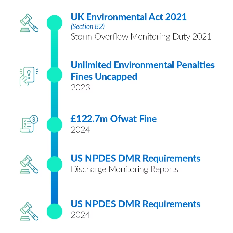
How Water Monitoring Systems Support Regulatory Standards
Why Connectivity Determines Confidence
Many remote river gauges, reservoirs, and discharge sites sit outside reliable cellular coverage. Even where coverage exists, service continuity can degrade during extreme weather, power disruption, or infrastructure failure. Total reliance on cellular connectivity introduces exposure.
Satellite IoT addresses this constraint directly. Low Earth Orbit (LEO) networks provide global coverage without dependence on local infrastructure. While satellite is not the right fit for every data profile, it offers coverage certainty where terrestrial networks cannot.
For message-based telemetry, Iridium Short Burst Data (SBD) supports low latency, small payload messaging suited to alarms, status updates, and exception-based reporting. That makes it particularly relevant where compliance-related events need to be captured and transmitted reliably from remote locations.
In practice, resilient remote monitoring often combines connectivity approaches to balance immediacy, scale, and power constraints. The examples below show what that can look like in water utility operations.
Case Study 1: Reservoir Monitoring and Remote Pump Control
The first example involves a remote reservoir that requires dependable monitoring and controlled pump activation despite unreliable cellular coverage. Two RockBLOCK RTUs were installed.
The upper unit measures water level and flow. It operates outside cellular range and uses Iridium SBD to transmit short command and status messages. When the water level is sufficient, it signals the lower RTU to activate the pump.
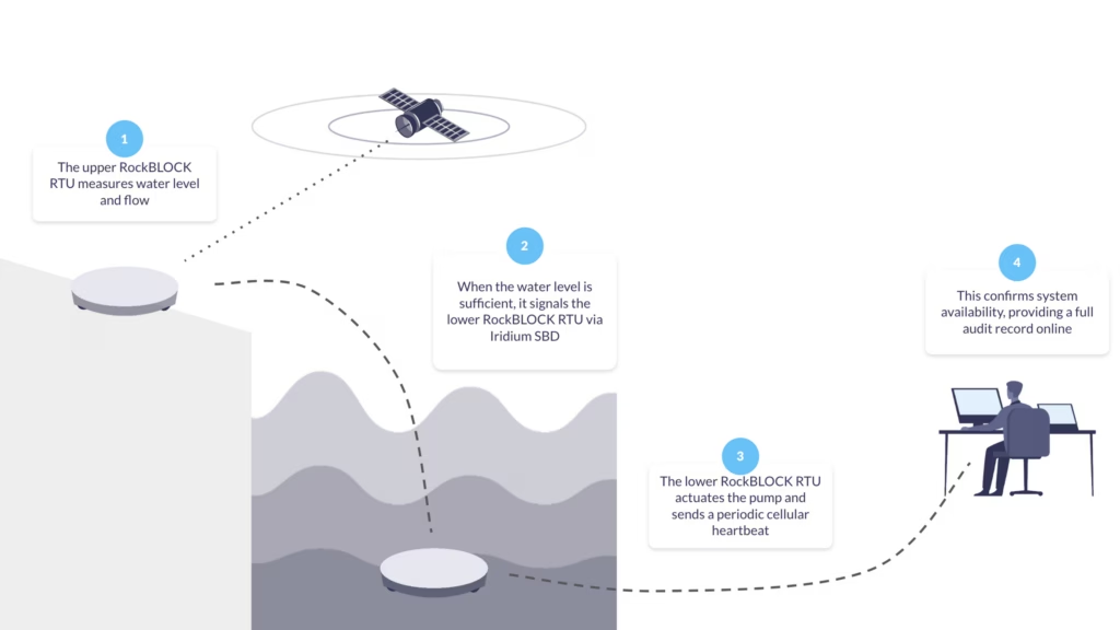
The lower RTU actuates the pump and sends a periodic cellular heartbeat to confirm system availability, providing near-real time confirmation of upstream conditions, controlled pump activation, documented event timestamps, and independent verification of site status.
From a compliance perspective, the Cloudloop platform retains a time sequenced record of level measurement, command transmission, pump activation, and heartbeat confirmation. Therefore, if questioned, the operational timeline can be reconstructed.
Case Study 2: River Health Monitoring With Micro Data Logging
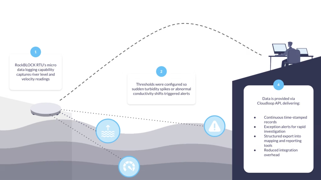
In our second deployment example, a local water authority needed to measure river level and velocity, derive discharge, and capture core water quality indicators. Rather than installing a full stand-alone data logger with integrated satellite comms, RockBLOCK RTU’s micro data logging capability was used to capture essential metrics.
Thresholds were configured so sudden turbidity spikes or abnormal conductivity shifts triggered alerts. Measurements flowed directly into the connected software via Cloudloop API integration.
This approach provided continuous, time-stamped records, exception alerts to support rapid investigation, structured export into mapping and reporting tools, and reduced integration overhead. For remote water monitoring more broadly, logging infrastructure and communications layers remain unified rather than fragmented across separate systems.
Building an Auditable Data Pathway
Confidence in remote water quality monitoring doesn’t come from a single device, but from the integrity of the whole data pathway. When time stamps are preserved across each layer, transmissions are acknowledged, and configuration changes are logged, reliance on manual consolidation falls, reducing errors and saving both time and money.
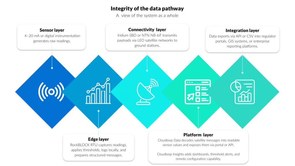
Auditability Across the Monitoring Chain
Within the layered architecture described above, the platform layer is where telemetry becomes a structured operational record.
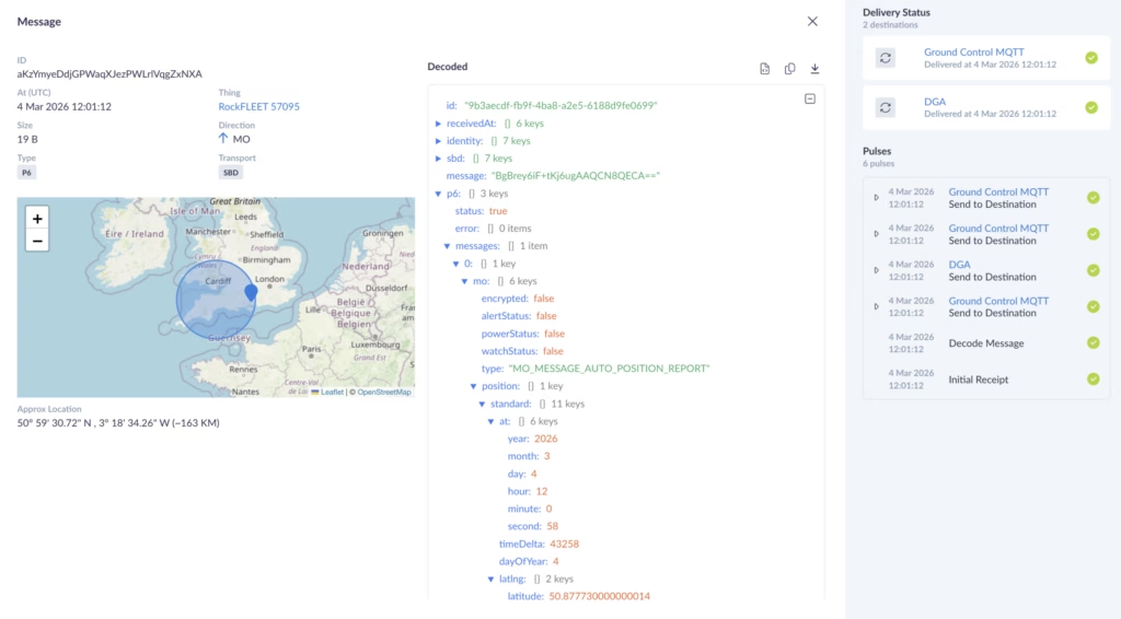
Cloudloop Data provides the ingestion and decoding layer between satellite transmission and operational systems. Messages received from RockBLOCK RTU are converted into readable sensor values, normalized, time stamped, and made available through a secure portal or API.
This removes the need to manage raw payload parsing internally and helps ensure each transmission is logged with the metadata needed for traceability, including device identity, transmission time, and delivery status.
In the reservoir monitoring example, level measurements, command triggers, and pump activation confirmations are preserved as a time-sequenced operational record.
In the river health deployment, turbidity and conductivity alerts are decoded and logged with consistent metadata before export into reporting and GIS tools.
Visualizing and Integrating Monitoring Data
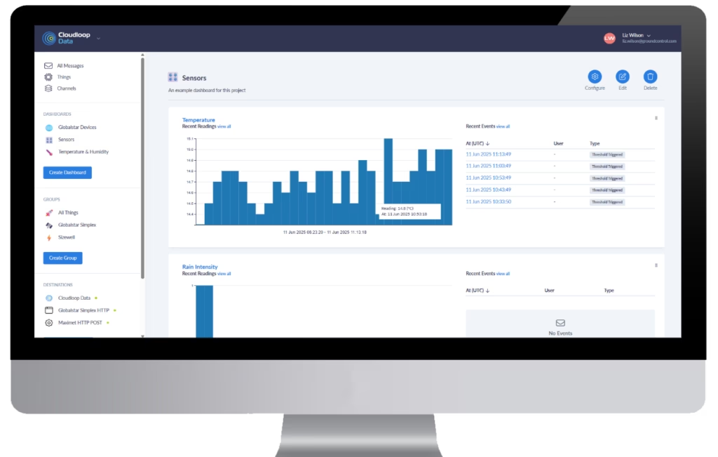
Cloudloop Insights builds on that structured data foundation by providing visualization, threshold configuration, and remote device control. Dashboards show both live and historical values, while threshold breaches, device status changes, and configuration updates are retained as part of the operational record, helping link system behavior back to defined monitoring parameters.
Both Cloudloop Data and Cloudloop Insights expose APIs, allowing telemetry and control data to flow into regulator submission tools, GIS environments, enterprise asset management systems, and custom EMS platforms. This API-first approach supports automated export for NPDES or UK reporting workflows, structured integration with mapping systems, programmatic access to historical telemetry, and closer alignment between remote measurement and institutional record-keeping.
As remote water quality monitoring comes under greater regulatory scrutiny and public visibility, monitoring systems need to support continuous measurement, structured reporting, and reconstructable data lineage across distributed, infrastructure poor environments. Together, these examples show how message-based satellite telemetry, edge logging, and structured platform integration can support compliance-grade monitoring.
Can we help?
If you are reviewing or upgrading a remote monitoring architecture, our Technical Solutions team can help assess site conditions, regulatory obligations, sensor requirements, latency needs, and audit trail completeness.
Complete the form or email hello@groundcontrol.com and we’ll get back to you within one working day.
Infographic: Why Remote Environmental Monitoring Systems Fail
Plus, How to Create Long Term Monitoring Stability
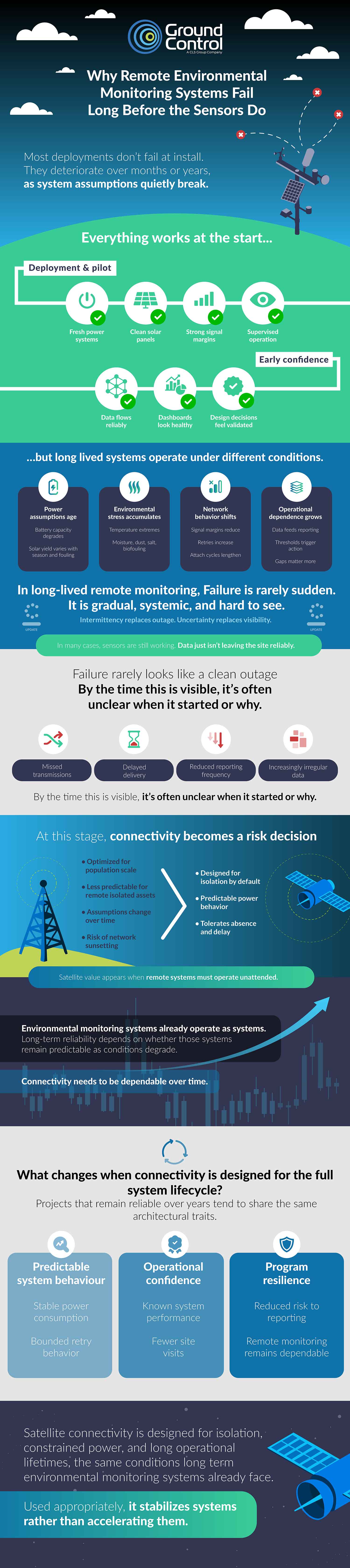
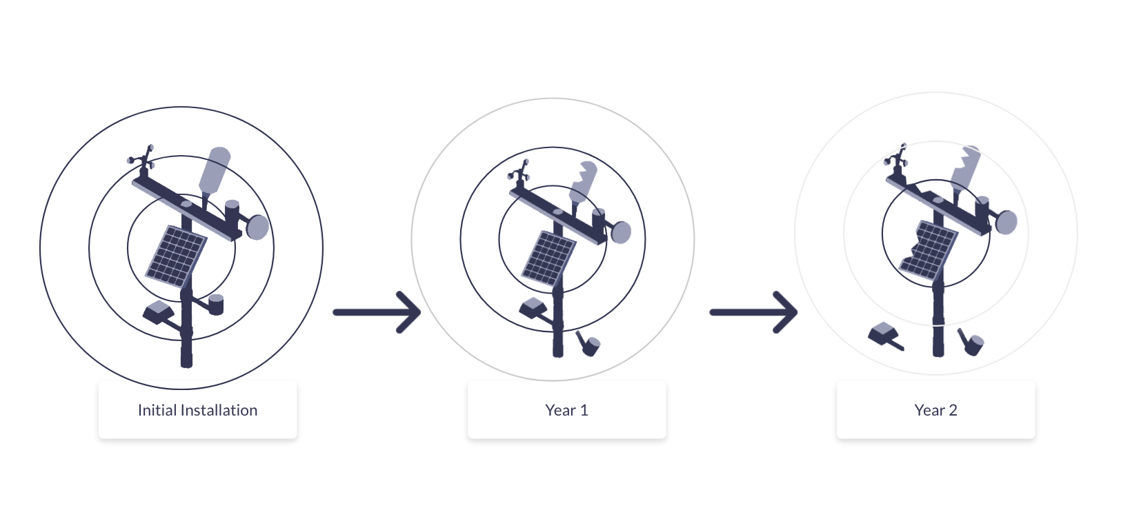
Remote environmental monitoring systems rarely fail all at once. Performance erodes gradually; data gaps widen, devices fall offline intermittently, power budgets tighten, and maintenance intervals shrink. Over time, reliability drops below what the original design assumed. The infographic below summarizes the most common technical and operational factors behind that decline, based on long term field observations across utilities and remote environmental monitoring deployments.
Many of these patterns may be familiar to you, yet their cumulative impact over five to ten years is less visible. Long term degradation is typically captured in post-mortems, warranty data, and support logs rather than formal reporting, so systemic reliability issues are often inferred from truck rolls or unexplained data loss instead of addressed at the design stage. Connectivity selection, power design, enclosure strategy, and remote management capability all shape lifecycle performance. Understanding these failure modes helps frame more durable trade-offs early, particularly where hybrid cellular and satellite options are being considered.
Helping OEMs Choose
For sensor OEMs, long term reliability increasingly shapes product selection and channel acceptance. Coverage variability, power constraints, integration overhead, and regulatory requirements all influence whether satellite or hybrid connectivity is commercially viable within your portfolio.
Our Environmental Sensor OEM connectivity guide outlines practical integration models, device classes, lifecycle considerations, and where satellite and hybrid designs materially reduce field failure risk. It is structured to support internal technical and commercial evaluation.
View Guide
Designing for Long Term Remote System Performance
If you’re designing for durable performance over the full deployment lifecycle of your remote environmental monitoring system, that means balancing coverage, power budget, data volume, enclosure design, remote management, and maintenance costs before scale amplifies weaknesses.
Satellite and hybrid architectures introduce different trade-offs depending on reporting frequency, firmware strategy, and site accessibility. Reviewing these options early helps reduce unplanned site visits and sustain data continuity over years, not quarters.
We’ve written more about this in our blog: Designing for Power and Reliable Data Delivery Under Uncertain Connectivity.
Find out more
If you are reviewing a current deployment or planning a new one, we can provide structured technical input based on your use case, power constraints, data profile, and coverage requirements. We design and manufacture our own devices and also support third party satellite hardware, so recommendations are aligned to lifecycle performance rather than a single product line.
If you complete the form with a brief outline of your application and constraints, a member of our engineering or technical support team will respond with impartial, practical guidance.
First Look at the New Iridium 9604 Module: What’s Changed from the 9603?
Iridium have just announced that they’ll launch their latest satellite IoT transceiver, the Iridium 9604, in June 2026. We’re exploring how this differs from its immediate predecessor, the 9603, and its “big brother”, the Iridium Certus 9704 module.
What is the Iridium 9604 module?
Iridium 9604 is a satellite IoT transceiver that utilizes Iridium’s Short Burst Data (SBD) service to send small volumes of data from remote applications operating outside cellular coverage.
In addition to SBD the 9604 module can also transmit using LTE-M cellular connectivity, making it ideal for mobile applications that cross in and out of cellular coverage, or where cellular coverage is unreliable, so a satellite failover is beneficial. The device doesn’t force automatic switching; it’s up to application developers to enable either simple failover rules or more advanced routing logic.
The 9604 module also features integrated GNSS (multi-constellation: GPS/GLONASS/Galileo/BeiDou), making it well-suited for tracking as well as IoT applications.
What Applications are Suited to the 9604?
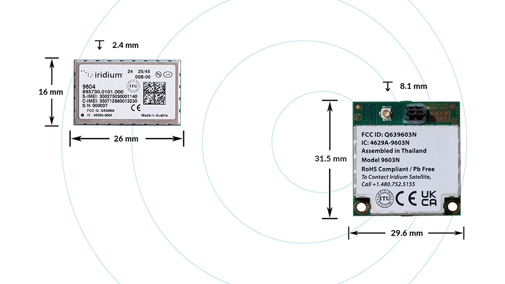
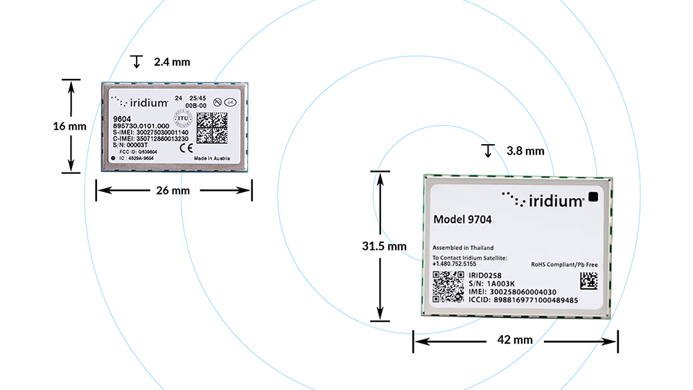
The new 9604 module is extremely small, measuring just 16 x 26 x 2.4 mm; the weight hasn’t yet been released but we can assume it will be similarly tiny. And while we don’t yet have detailed specifications,, Iridium have stated that it is designed for ultra low power applications.
Any mobile remote IoT application constrained by size, weight and power – e.g. drones/UAVs, animal tracking, data buoys, autonomous machinery – will benefit from the 9604’s form factor and dual-mode satellite/cellular capabilities.
How Does the 9604 Differ from the 9603 Transceiver?
- Connectivity: the 9603N uses Iridium SBD (340 bytes transmit; 270 bytes receive), as does the 9604, however the 9604 also adds LTE-M connectivity.
- Tracking: the 9603N needs to be paired with a separate GNSS receiver to transmit a location, whereas this capability is built into the 9604.
- Form factor: the 9603N measures 31.5 mm × 29.6 mm × 8.1 mm vs. the 9604’s 16 x 26 x 2.4 mm.
Will it be Easy to Upgrade from 9603 to 9604?
We anticipate a lot of teams will want to keep their familiar SBD workflow, but add cellular opportunism. We will be available to help make this migration process simple. And for teams outgrowing SBD message sizes, we can help make the jump from SBD to IMT.
How Does the 9604 Differ from the 9704 Transceiver?
Iridium relatively recently launched the Certus 9704 satellite IoT transceiver (December 2024), and the 9604 is not a direct competitor or successor to this device. 9604 is about hybrid connectivity for small messages, while 9704 is about bigger payloads.
The 9704 utilizes Iridium Messaging Transport (IMT), which will transmit up to 100 KB per message; up to the challenge of sending aggregated gateway data, audio, and compressed images. The 9604 uses Short Burst Data (SBD), which is intended for extremely small messages (340 bytes transmit / 270 bytes receive).
The 9704 module is larger – 31.5 mm × 42.0 mm × 3.8 mm – and does not have built-in GNSS or cellular capabilities; it is intended for fully remote deployments where you still need meaningful data volume.
Choose the 9604 if you’re sending small messages frequently; if you’ll benefit from its hybrid connectivity, and if your goal is optimized cost/performance in mixed coverage regions.
Which Devices Utilize the 9604 Transceiver?
We’re part of Iridium’s beta program, leveraging our decades of experience working with Iridium modules to build customer solutions that make it easy to benefit from the 9604’s extra capabilities – hybrid connectivity, low power consumption, and a tiny form factor.
Both the bare module and the Ground Control solutions will be integrated into Cloudloop, our cloud-based, API-first IoT platform which manages subscriptions, devices and data. Cloudloop Data is particularly useful for systems integrators, as it seamlessly routes uplinks and downlinks to your HTTPS or MQTT endpoint, and exposes a REST API and dashboard for device metadata, transmission status, and message history.
How to Get Started
We encourage you to contact us to discuss your application; we are Iridium experts, and will provide you with impartial advice on the best airtime, service and hardware to best meet your needs.
Fill in the form or email hello@groundcontrol.com, and we’ll reply within one working day.
The Six Costliest Remote IoT Integration Mistakes (and How to Avoid Them)
Remote IoT looks straightforward until you hit the realities of variable latency, tight data budgets, and devices you can’t easily reach once deployed.
This free and ungated eBook distills the integration pitfalls Ground Control sees most often, plus the practical patterns that help teams go live faster and stay operational long after launch.
It’s written for IoT product and platform teams, systems integrators and solution architects, operations and field deployment leaders, and security/IT stakeholders supporting remote infrastructure.
Read Free eBook
What’s Inside: The Six Costliest Integration Mistakes
1. Security & IT Reality Checks
Satellite links can be strongly encrypted, but risk often concentrates at the handoffs, where data routes from the ground segment into your cloud / application environment.
The eBook outlines common postures (VPN + firewalls, private circuits, or higher-isolation architectures) and the blockers that derail projects late.
Fast takeaway: map the end to end path, choose the security posture deliberately, define ownership, and pre-empt IP range conflicts/timeouts before they become downtime.


2. Interoperability Isn’t Automatic
Remote IoT punishes cellular assumptions. The economics change when every transmission costs power, airtime, and often money.
This chapter shows how teams avoid brittle integrations by designing around constraints: a minimal payload strategy, a clear send policy, and ingestion built for compact messages.
Fast takeaway: prioritize purposeful messages and treat the translation layer as critical infrastructure – version it, test it, and monitor it.
3. The Field Will Prove You Wrong
Coverage maps don’t guarantee performance. Antenna placement, terrain, structures, and foliage create real world RF failure modes.
The eBook clarifies the difference between ‘clear view of the sky’ (LEO satellites) and ‘line of sight’ (GEO satellites), and why confusing these leads to broken installs.
Fast takeaway: validate sky view at the true install height, and test in the actual environment before you scale.


4. Design For Delays, Not Perfection
Message-based satellite IoT doesn’t behave like web or cellular. Systems fail when they assume instant confirmation and tight timeouts.
This chapter explains the ‘accepted vs delivered’ distinction and why retries, buffering, and correct acknowledgements are foundational.
Fast takeaway: use jitter + backoff, implement store and forward properly, and only return ‘success’ after durable storage.
5. Lifecycle and Remote Device Management
Remote device management traffic competes with mission data – reboots, logs, config reads, and updates all consume power and paid data.
The eBook covers how teams avoid slow-motion failures by separating ‘alive’ from ‘healthy’, controlling configuration drift, and planning staged updates.
Fast takeaway: treat configuration like code, budget for ops traffic, and design a real end of life workflow.
6. Data Discipline in Constrained Connectivity
Most systems can produce far more telemetry than anyone will ever use, and ‘send everything’ is the fastest way to lose control of battery life and budgets.
This chapter gives practical patterns like exception reporting, edge summaries, payload compaction, and ruthless prioritization so you protect what matters most.
Fast takeaway: define the smallest information set that drives decisions, then budget size/frequency/retry rules by priority tier.
Key Outcomes You Can Expect
By the end, you’ll be able to spot the integration choices most likely to cause schedule slip and rework, set realistic expectations for latency, delivery confirmation, and retries, and build payload and send policies that scale economically.
You’ll also learn how to reduce truck rolls by designing lifecycle management in from day one, and how to pressure test your deployment plan before you scale it.
The core theme throughout is simple: design for operations, not just installation.
Read the eBook before you make your next integration decision
Get the PDF immediately (ungated). It covers security handoffs, interoperability, field RF realities, latency/retries, device lifecycle, and data discipline.
Read Free eBookWant help pressure testing your integration plan?
If you’re planning a remote deployment and want to validate your architecture, data budget, or rollout approach, we can help you identify risk early – before it becomes field rework.
Contact Our ExpertsFAQs
It’s written for remote deployments where constraints matter most – satellite and hybrid deployments in particular – but the integration lessons apply broadly to any system where latency, cost, power, and field access are real constraints.
Yes. Several chapters focus on operational issues that appear after launch (retries, lifecycle management, configuration drift, and data discipline).
Yes. Each chapter ends with concrete takeaways (e.g., security mapping and ownership, field testing non-negotiables, ‘slow link’ checklist, and data discipline checklist).
Have a remote IoT project to discuss?
No need to contact us to read the eBook – but if you want to chat about your remote IoT project, we’d love to hear what you’re working on.
Complete the form or email hello@groundcontrol.com with your application details, and we’ll connect you with one of our expert team to see if we can support your goals.
Designing for Power and Reliable Data Delivery Under Uncertain Connectivity
If you integrate remote environmental monitoring systems, you will eventually encounter a site where connectivity becomes the dominant uncertainty. Sensors continue to sample correctly. Local electronics remain operational. Yet data delivery becomes intermittent or unpredictable. In many cases, the issue is not outright loss of coverage, but changing network conditions at sites that were always near the edge of what terrestrial connectivity could reliably support.
At that point, the problem shifts. It’s no longer about sensor selection or firmware optimization, but rather a system design question: how do you maintain low power operation and predictable data delivery when network behavior cannot be assumed to be stable over time? This is where system integrators typically start comparing architectural options rather than individual bearers.
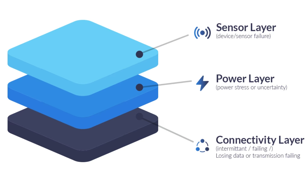
The first of these options is terrestrial cellular, using LTE-M or NB-IoT, where coverage is stable and well characterised over time. The second is proprietary satellite connectivity, where coverage reach and low duty cycle operation are prioritized over throughput. The third, emerging option is Non Terrestrial Network (NTN) NB-IoT, defined in 3GPP Release 17, which aims to extend cellular standards beyond terrestrial infrastructure using satellite networks.
Each model behaves differently at the system level. None is universally good or bad. The challenge for the system integrator is determining which operating envelope matches the realities of a given deployment.
A Practical Decision Framework for Remote Monitoring Sites
In practice, connectivity decisions are best framed around a small number of system-level criteria:
- How stable is coverage over seasons, vegetation cycles, and weather, not just at installation?
- How defensible does the connectivity choice need to be over a multi-year deployment?
- Is the team building a custom node, or does it prefer an integrated monitoring device?
- How constrained is power, and how expensive is site access if batteries deplete early?
- What is the expected payload size per reporting interval?
- How often does the device need to wake and transmit, and how tolerant is the application to latency?
In remote environmental monitoring, these questions are often more predictive of long term system than headline bandwidth figures or nominal coverage maps. They surface how connectivity behaves over time, how often radios wake, and how energy is actually consumed under real site conditions.
Technical Connectivity Matrix
The matrix below helps match connectivity options to their most defensible operating envelopes, and is most useful when applied to site conditions rather than connectivity technologies in isolation. In marginal or variable RF, devices may spend longer acquiring the network and retrying transmissions, which increases energy consumption and reduces delivery reliability / latency predictability. Those risks can matter as much as nominal coverage.
| Cellular NB-IoT | Proprietary Satellite* | NTN NB-IoT** | |
|---|---|---|---|
| Primary Strength | Lowest cost per KB; high throughput | Global reach; predictable power profile | Converged hardware model; emerging reach |
| Coverage Stability | Variable at cell edges; sensitive to vegetation | High, assuming hemispherical sky view | Emerging; constellation dependent |
| Low Power Operating Modes and Sleep Opportunity | Supports PSM (very low average possible), but sleep opportunity depends on operator timers + coverage | Supports true deep sleep via power gating between scheduled bursts (system design dependent) | Early estimates ~10–50 µA |
| Transmit Load Profile | TX current is variable (uplink power control, coverage enhancement). Worst case energy / on time can increase due to repetitions, attach / resume behavior, and retries | TX is typically short burst transmissions with an implementation defined retry cap; peak can be amp class depending on module / rail, but event duration and attempt count can be tightly bounded | Low power operation expected; current figures are highly implementation- and network-dependent |
| Max Practical Payload | 1,400-1,600 bytes | 100 KB | 1,200 bytes |
| Min Practical Payload | 30-50 bytes | 10 bytes | 10-30 bytes |
| Typical Latency | ~100 ms to several seconds | ~10 seconds | 10 – 60s; MVNO scheduling could increase this to 2 – 5 mins) |
| Risk Factors | Network maintenance signalling and retries in marginal RF | Relatively high peak current; antenna placement and sky visibility | Immature ecosystem; coverage and delivery reliability still variable / under validation (latency and transaction timing may be less predictable than terrestrial) |
| Deployment Status | Mature and ubiquitous | Mature and proven | Early commercial trials |
*Based on Iridium Messaging Transport (IMT)
**Based on Viasat NB-NTN service – specification subject to change
Why Connectivity Dominates Lifetime Uncertainty
Long life environmental monitoring nodes are designed to sleep almost all the time because field power is expensive; whether that’s truck rolls for batteries or solar constrained by canopy, weather, latitude, and vandalism risk.
In most deployments, the sensing and compute workload is predictable and easy to budget. What’s harder to budget is communications: acquisition time, repetitions / retries, and delivery uncertainty can swing dramatically with site RF conditions and seasonality. That variability often becomes the biggest driver of both battery life uncertainty and operational reliability, more so than the sensor workload itself.
How Terrestrial Cellular Behaves in Remote Environments
Cellular connectivity performs well when coverage is stable and predictable. In those conditions, LTE-M and NB-IoT are often the most cost effective and operationally simple choice.
Challenges arise in remote environments where coverage quality fluctuates rather than failing completely. Field experience from utilities, water monitoring, and environmental telemetry deployments shows that link conditions at unattended sites often vary over time due to terrain, vegetation growth, weather, and seasonal effects, even when initial installation is successful.
From a power perspective, this variability matters. Under marginal coverage conditions, devices may attempt repeated attachment or transmission cycles before successful delivery. These retries consume energy without proportional data transfer.
Operationally, this can result in systems that appear functional but are difficult to predict. Batteries deplete faster than expected, and data gaps are harder to diagnose remotely. This does not mean cellular is unsuitable for remote monitoring. It highlights the importance of understanding how cellular behavior evolves within a specific deployment context, particularly at marginal coverage sites where energy risk can be as significant as coverage risk.
If your design needs predictable energy and diagnosability under uncertain RF, you may prefer a connectivity model that is explicitly scheduled and bounded: this is the key shift introduced by satellite IoT.
How Satellite IoT Architectures Change System Assumptions
Satellite IoT spans two broad architectural models: message-based services (store and forward / burst messaging) and IP-based services. Message-based links are naturally aligned to low duty cycles: devices wake on an application defined schedule to transmit a small payload, optionally open a short receive window, and then return to deep sleep. In this model there is no requirement for continuous “always-on” participation, and average energy use is closely coupled to reporting cadence, retry policy, and power domain design.
IP-based satellite terminals can provide richer connectivity and more interactive downlink, but may incur additional idle overhead to maintain readiness or session behavior, even when user traffic is low.
For long life environmental monitoring, the most defensible operating envelope is typically scheduled messaging with deep sleep between sessions, not continuous reachability. The remainder of this post therefore focuses on message-based satellite IoT, and on implementation patterns that make the comms link behave like any other managed subsystem with predictable states and budgets. We start with Iridium Messaging Transport (IMT) via RockBLOCK modules (particularly the 9704), as it fits naturally into a wake > transmit > sleep design.
Implementation path one: Message-based satcom as a managed subsystem (RockBLOCK 9704)
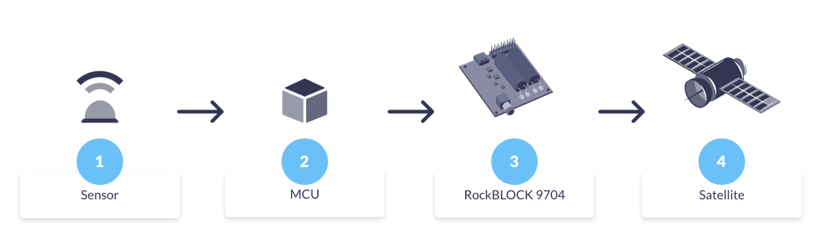
RockBLOCK 9704 is built around the Iridium Certus 9704 module and uses Iridium Messaging Transport (IMT): a cloud connected, two way messaging service for small to moderate payloads (up to ~100 KB) designed for IoT devices rather than continuous IP sessions.
In a long life monitoring node, it’s best treated as a schedulable subsystem inside a wider embedded design. In practice, integrators typically:
- Power-gate the modem (load switch/PMIC) so “off” is truly off
- Wake it only after sampling / validation, when there’s something worth sending
- Transmit in short, scheduled sessions, with an explicit retry policy
- Return to deep sleep (or fully unpowered) immediately after the exchange.
The key engineering advantage is boundedness: reporting cadence, session timing, and retry limits are largely under host control, so you can model energy around a small set of well defined states (off / boot / transmit / receive window).
Peak transmit current can be high because closing a link to a LEO constellation requires substantial instantaneous RF power. In a messaging oriented design this draw occurs in short, intentional transmit bursts with bounded duration. The design trade shifts from minimising peak current to ensuring the power system comfortably supports short peaks (battery internal resistance, regulator headroom, local capacitance), while keeping average energy dominated by how often you transmit.
RockBLOCK 9704 doesn’t manage your sensor rails or MCU sleep states – those remain the job of the embedded design – so standard low power techniques (switched sensor rails, unpowered analog front ends outside measurement windows) still apply.
Because IMT is a two way messaging service, you can make delivery outcomes explicit at the application layer: buffer locally, send, then check for confirmation on the next scheduled wake window, without keeping the node awake. This keeps reliability mechanisms aligned with the same duty cycled philosophy as sensing. The important caveat is that network availability (constellation / service uptime) is not the same as guaranteed delivery in every installation: local RF conditions still dominate, i.e. sky view, canopy, terrain, enclosure losses, and antenna placement.
That integration pattern works well when you’re building your own node around a messaging modem. When you’d rather avoid custom hardware and firmware integration, the same principles can be applied at the system level:
Implementation path two: RockBLOCK RTU as an integrated low power monitoring device
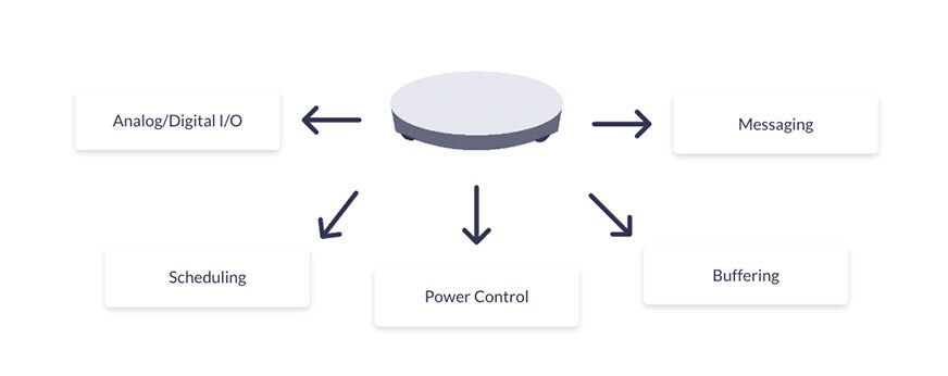
If you don’t want to integrate and power manage a satcom module inside your own node, RockBLOCK RTU packages the same sleep dominant principles at the system level: sensing, scheduling, local buffering, and messaging in one device. RockBLOCK RTU uses Iridium Short Burst Data (SBD), Iridium’s classic two way short-packet messaging service, so it naturally fits duty cycled environmental monitoring workloads.
RockBLOCK RTU is designed around a sleep dominant lifecycle:
- Extended low power sleep as the default state
- Wake events driven by schedule, thresholds, or external triggers
- Short transmission windows
- Immediate return to sleep.
Sensor power is explicitly controlled so sensors are energised only during measurement windows, eliminating standing analog bias currents. This mirrors best practice low power sensor design without requiring custom analog switching. Because message-based satellite operation can be scheduled without continuous reachability, RockBLOCK RTU avoids some of the standing ‘network-reachable’ overhead that can appear in terrestrial designs (depending on configuration and coverage).
In addition to sensing, RockBLOCK RTU provides system level control and observability that are often important in unattended deployments. Configurable digital outputs can switch sensor power rails or external loads, and analog inputs can monitor system voltages (battery, supply rails, excitation lines).
This enables remote verification of power health, detection of brownout conditions, and confirmation that sensors are energised only when expected, helping distinguish sensing issues, power delivery problems, and comms failures without site access.
Time Alignment and Operational Visibility
A recurring operational challenge in unattended monitoring is ambiguity: when data is missing, it’s often unclear whether the system failed to measure or failed to report. RockBLOCK RTU reduces this ambiguity with an internal clock and UTC-aligned timestamps (GNSS when available), making it easier to correlate measurements with expected reporting intervals and separate sensing gaps from delivery failures.
When Proprietary Messaging Satcom is Usually the Wrong Tool
Message-based proprietary satellite IoT is optimized for predictable, low duty telemetry – not high volume data or near real time streaming. Where cellular coverage is stable and power is plentiful, terrestrial LPWAN/cellular often remains the simplest and most cost effective option.
The interesting middle ground is NTN NB-IoT, which aims to extend cellular-style connectivity via satellite, so it’s worth understanding how much of the terrestrial behavior (and variability) it inherits.
NTN NB-IoT as an Emerging Option
Non-Terrestrial Network (NTN) NB-IoT, standardized in 3GPP Release 17, extends familiar NB-IoT device and core concepts to satellite links and is often framed as a bridge between terrestrial cellular and proprietary satellite IoT.
For environmental monitoring engineers, the key point is the capability shape: NTN NB-IoT is still fundamentally a low data, latency tolerant telemetry channel , not a streaming link , while aiming to preserve cellular style device models and tooling.
Commercially, it remains an emerging option: footprints, roaming models, and integration paths are operator and region dependent, and multi year public field data on power variance and failure modes is still limited compared with mature terrestrial PSM deployments. That doesn’t imply worse power performance; only that it’s harder (today) to treat it as a fully characterized default for unattended multi-year deployments.
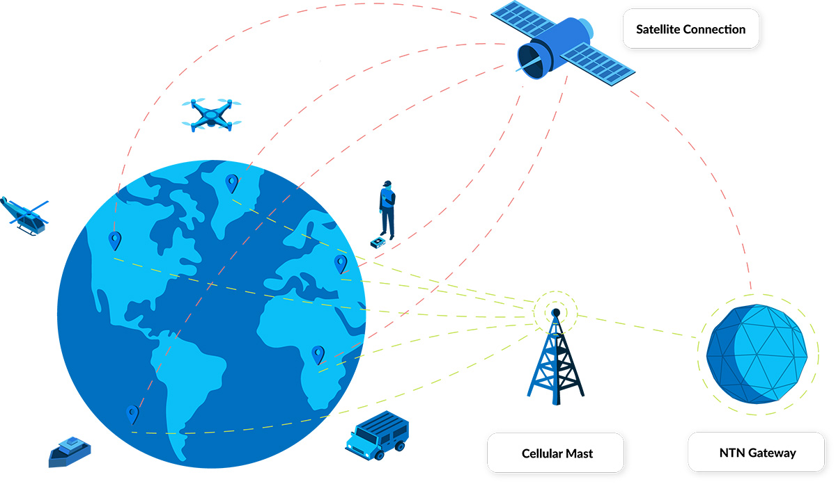
As an illustrative example, Viasat’s NB-NTN positioning is bidirectional messaging with practical payloads around 10–30 bytes up to ~1,200 bytes, typical latency on the order of 10–60 seconds (potentially minutes depending on scheduling), and cost optimized for very small monthly data volumes (e.g., <50 KB).
One implementation detail worth flagging is NIDD (Non-IP Data Delivery). Where supported end to end by the operator and device stack, NIDD can reduce protocol overhead for tiny messages versus UDP/IP, which can materially help battery life at scale; but it’s worth confirming early whether your chosen NTN integration path actually exposes it in practice.
RockBLOCK RTU and NTN Evaluation Paths
An NTN-enabled RockBLOCK RTU is being used in early programs on Viasat’s NB-NTN service. The point isn’t that NTN performance is already fully proven; it’s that you can test and measure it using a monitoring device with a known low power architecture and good instrumentation.
Because RockBLOCK RTU already implements a sleep-dominant lifecycle (scheduled wake, short transmit windows, controlled sensor power, UTC-aligned timestamps, and supply-voltage monitoring), it provides a consistent baseline for evaluating NTN energy use, delivery timing, and variability without redesigning the sensing node.
If you’re considering NTN NB-IoT for an environmental monitoring deployment, Ground Control can support trial deployments and share an evaluation plan.
Practical Implications for System Integrators
For system integrators working in remote environmental monitoring, connectivity decisions are rarely static. Alignment between duty cycle, power constraints, coverage stability, and operational risk tends to determine long term system performance.
Cellular, proprietary satellite messaging services, and NTN NB-IoT each occupy different operating envelopes. Understanding those differences enables decisions to be defended throughout the lifecycle of a deployment.
Where coverage stability cannot be assumed, satellite connectivity provides an architectural alternative that aligns well with how low power remote monitoring systems are typically designed to operate. NTN NB-IoT represents a promising but still emerging option, particularly in contexts where long-term unattended power and reliability characteristics are still being established.
Planning for Intermittent Connectivity is a System Decision.
If you’re assessing where proprietary satellite, NTN NB-IoT, or hybrid connectivity fits into your architecture, we can help you evaluate the trade offs early, before reliability or power becomes the constraint.
Complete the form, or email hello@groundcontrol.com and we’ll reply within one working day.
UAV Satcom Architecture: When Messaging Fits Better Than Always-On IP
When OEM teams discuss satellite connectivity for UAVs, the conversation often defaults to IP. It feels familiar, maps neatly to ‘internet-like’ thinking, and enables genuinely interactive workflows. And if your primary link is cellular, you’re usually already living in an IP world, so using an IP-based satellite service can look like the cleanest way to add failover comms without changing the application stack.
There’s also a second, equally valid pattern that many UAV architectures underuse: message-based transport. Used intentionally, it gives you a delivery oriented path for critical data, well suited to situations where connectivity can be variable and you want the system to behave calmly through brief fades. Further, if you’re tight on payload and battery, messaging can be the better fit in practice because the terminals are typically smaller, lighter, and lower power.
In real operations, links do get imperfect; often briefly, sometimes repeatedly. The question isn’t whether IP or messaging is better. The question is: what should your system do when connectivity becomes intermittent?
Intermittency is Normal in UAV Satcom
Irrespective of your choice of satellite network, satellite connectivity is shaped by installation choices and the operational environment. You may see brief fades or dropouts caused by antenna placement and orientation (vehicle attitude, manoeuvring, installation constraints), airframe shadowing (the drone itself blocking sky view), and terrain or obstructions (especially at lower altitudes). These aren’t exotic edge cases; they’re part of the everyday reality of airborne links.
Designing for that reality is less about chasing a perfect connection, and more about choosing link behaviors that match the data you need to move.
| IP (interactive session) | Messaging (queued delivery) | |
|---|---|---|
| Best for | Operator driven workflows and interactive payload control | Delivery oriented updates and 'must get through' messages |
| Typical pattern | Continuous back and forth | Discrete messages sent in packets |
| When the link fades briefly | Sessions may need reconnection / state re-establishment before resuming | Messages can be queued and retried according to your policy / service behavior |
| How to think about it | “Stay connected” | “Deliver this information” |
IP is Ideal for Interactive Sessions
An IP connection excels when you genuinely need an interactive session: operator driven workflows, higher touch payload control, and applications that depend on continuous back and forth.
Many IP applications also maintain session state and use keep-alives. When connectivity becomes intermittent, those session oriented behaviors may require reconnection and state re-establishment before the application resumes normal operation. That’s not a problem with IP; it’s simply how many interactive applications are designed.
In UAV satcom, where brief fades can be normal, it can be helpful to complement interactive IP workflows with a delivery oriented path for data that should still make progress even when the link isn’t perfectly continuous.
Messaging is Designed for Queued Delivery
Message-based transport starts from a different premise: you’re not trying to stay in an ongoing conversation. You’re trying to deliver discrete information, and you want the system to behave sensibly if conditions aren’t perfect at the moment you try to send.
In a well designed message-based workflow, you can queue data for delivery and apply an explicit retry policy, so brief fades don’t necessarily translate into a broken live session experience. Messaging doesn’t need to hold a session together to succeed; it just needs a window good enough to move the message, with delivery behavior determined by the service and by how you design your application logic.
Messaging is often a good fit for data types where you care about delivery and can tolerate brief delays, such as safety and control intents, periodic telemetry snapshots, mission state updates and compliance events, and ‘must get through’ alerts.
A useful practical point for OEMs: messaging aligns with how many UAV systems already work internally. Most aircraft already buffer, queue, and batch. Messaging extends that same logic across the link.
Treat Connectivity as Multiple Lanes, Not One Pipe
A helpful mental model is to stop choosing “IP vs messaging” as a single binary decision for the whole aircraft. Instead, choose by data type, and build lanes that match how that data behaves and what it’s worth.
Hardware reality (SWaP): These lanes often map to different terminal classes. Messaging modules can be palm sized and tens of grams, while IP terminals are commonly larger, heavier and higher peak power because they’re built to sustain a live session.
Lane 1: Tiny, decisive commands (SBD / RockBLOCK 9603)
Some messages are small because they should be small. When the message is ‘deliver the intent’, payload is not the point.
This is where Iridium Short Burst Data (SBD), delivered via RockBLOCK 9603, fits well: very small messages that can carry command and control intents such as stop, start, return to base, or critical state flags.
It’s an architecture move as much as a connectivity move: you’re creating a path for decisive actions that don’t require an ongoing live session to be valuable.
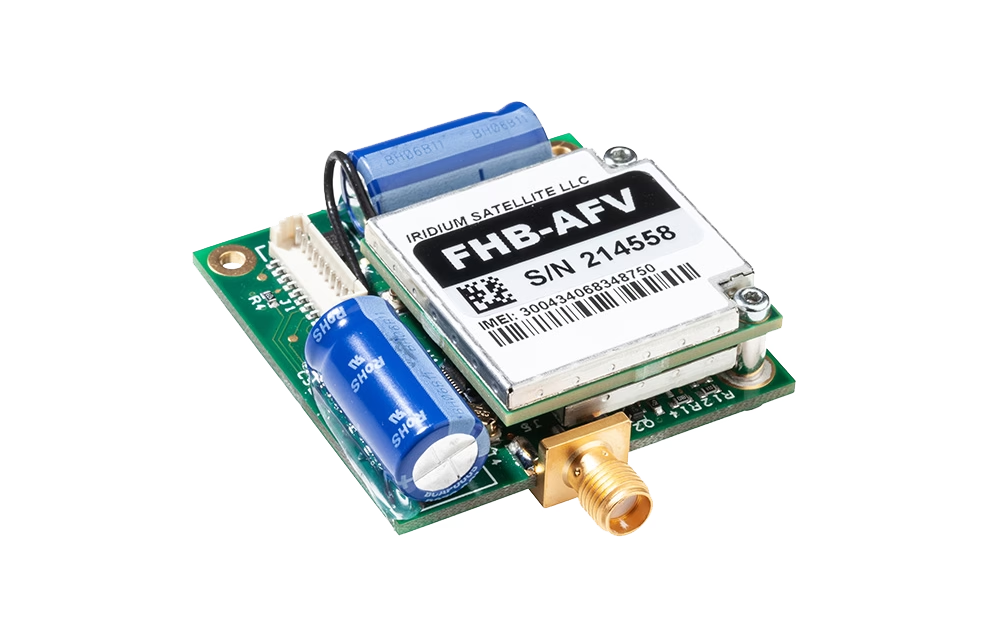
SWaP snapshot: RockBLOCK 9603 is 45 × 45 × 15 mm, 39 g (incl. antenna), max 450 mA; a good fit when you want deliver the intent with minimal payload and battery impact.
Lane 2: Larger discrete packets (IMT / RockBLOCK 9704)
Messaging becomes even more interesting when it isn’t constrained to tiny pings. With Iridium Messaging Transport (IMT), delivered via RockBLOCK 9704, you can work with larger messages (up to 100 KB). That’s enough to move more than bare minimum telemetry.
For many OEM designs, it opens the door to a straightforward pattern: collect richer data onboard (as you already do), then transmit it as structured packets – telemetry snapshots, compressed logs, payload summaries, detection events – according to a schedule and policy that fits the mission. Instead of ‘keep the pipe open’, the goal becomes ‘move the next packet when conditions allow’, with clear application logic around queueing, acknowledgement, and retry.
This approach can be a good match for how operators actually use data: many decisions don’t require millisecond streaming; they require timely, trustworthy updates that arrive consistently.
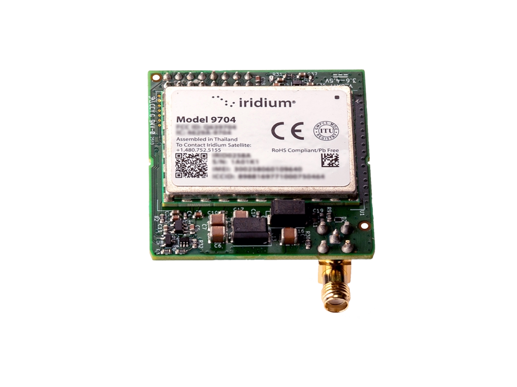
SWaP snapshot: RockBLOCK 9704 (SMA) is 48 × 52 × 16 mm, <35 g (excl. antenna), max 1.4 W; still firmly in the small and light messaging class.
Lane 3: Interactive workflows (Certus 100 / RockREMOTE UAV OEM)
When you truly need a live interactive link, IP is absolutely the right tool.
That’s where Iridium Certus 100, delivered via RockREMOTE UAV OEM, comes in. For OEMs, the appeal is flexibility at the system level: you can support an IP-based connection for interactive workflows, while also designing message-based IMT workflows for data types that benefit from queued, delivery oriented transport, without forcing every workload through a single paradigm.
The result is a more intentional architecture: interactive applications use IP when they need to, and delivery oriented data uses messaging patterns when that better matches the operational reality.

Trade-off (SWaP): RockREMOTE UAV OEM is 175 × 60 × 37 mm, 287 g, peak <1.66 A @ 12 V or <833 mA @ 24 V (≈ 20 W peak); worth it when you truly need an interactive link, but a meaningful step up in size / weight / power versus messaging modules.
The OEM Decision: What Happens During a 30 Second Fade?
Here’s a simple test that clarifies architecture decisions fast. Picture a brief period where conditions degrade: antenna orientation changes during a manoeuvre, the airframe masks sky view, or the aircraft drops behind terrain. It’s not a total outage, but the link becomes unreliable.
Now ask: what should your system do? If the data is interactive, it’s reasonable for the experience to be interrupted. The operator understands that continuous live control isn’t guaranteed in all conditions.
If the data is delivery-oriented, especially safety, health, compliance, or mission state, then the system should behave calmly: queue, send when it can, and retry according to your service behaviour and your application’s retry policy.
That’s the core difference in mindset: designing for interactivity versus designing for delivery.

Messaging
Use messaging first when the requirement is: ‘this must get through, even if it arrives later than a live dashboard would prefer’.

IP
Use IP first when the requirement is: ‘a human or application must interact continuously’.
Combined
Use both when you want the best operational outcome: IP for interactivity, messaging for delivery oriented updates and structured packets.
The strongest OEM architectures rarely treat connectivity as one monolithic pipe. They treat it as a set of behaviors, each aligned to what the data is for.
Bottom Line: Choose by Data Type, and Design for Real Operations
IP is excellent when you need live interactivity. Messaging is well suited to delivery oriented updates when conditions are variable and you want a queued approach with an explicit retry policy. Hybrid designs let you use each where it fits best: IP for interactive moments, messaging patterns for critical updates and structured packets.
If you’re designing for real operations, and not just ideal lab conditions, message-based transport deserves consideration early in the architecture, alongside IP, rather than as an afterthought.
Disclaimer: real world performance depends on system design, antenna integration, operational environment, and service configuration; the right approach is mission- and data-dependent.
Talk through your satcom architecture with us
Email us at hello@groundcontrol.com, or complete the form, with your details and a couple of lines about your platform (airframe class, typical mission profile, and what data you need to move).
We’ll follow up with practical guidance on where SBD (RockBLOCK 9603), IMT (RockBLOCK 9704), and Certus 100 (RockREMOTE UAV OEM) fit in your architecture, and how to combine them for an operator-friendly design.
Snow, Ice and No Signal Bars: Where Satellite IoT Steps In
When winter bites, the world doesn’t stop moving. Researchers crunch climate data at 6,500 meters. Ships weave through drifting icebergs. Volunteers groom snowmobile trails through the night. Pilots fly over whiteout terrain. Rivers swell with snowmelt and threaten nearby communities.
In all of these places, terrestrial connectivity is patchy, or simply doesn’t exist. From Himalayan glaciers to Arctic sea ice and winter trails, Ground Control’s satellite IoT and tracking services keep people, assets and data connected when the temperature drops and terrestrial networks disappear.
We’ve brought together five real world winter operations where satellite IoT quietly gets the job done.
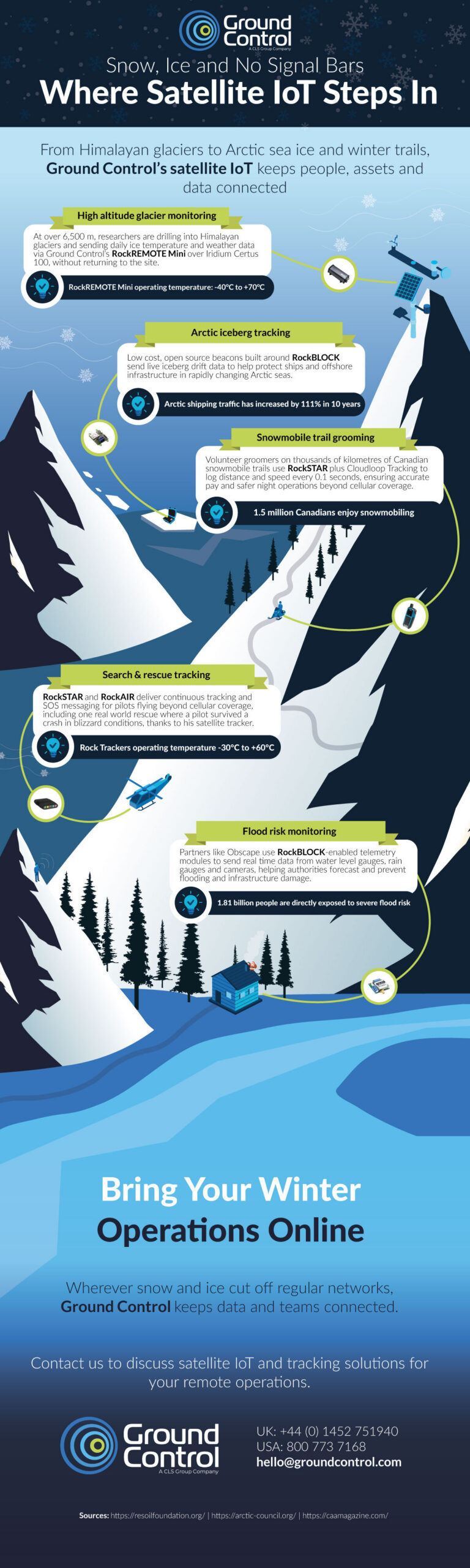
High Altitude Glacier Monitoring on Everest
At extreme elevations, there are no engineers on call, no cell towers on the skyline, and not much margin for error. Yet these are exactly the locations where climate scientists need reliable, continuous data.
On Himalayan glaciers, researchers are deploying autonomous stations that can operate for months at a time without human intervention.
Using Ground Control’s RockREMOTE Mini over the Iridium Certus 100 network, these stations send back daily information on ice temperature and local weather conditions.
That data helps scientists understand how fast glaciers are melting, how conditions are changing over time, and what that means for the communities that rely on these frozen reservoirs downstream.
Arctic Iceberg Tracking for Safer Seas
In the Arctic, winter never really leaves, and the landscape is in constant motion. Icebergs calve from glaciers and drift through busy shipping lanes and past critical offshore infrastructure. For vessels and platforms operating in these waters, knowing where the ice is, and where it’s heading, is essential.
Teams working in this environment are deploying low cost, open source beacons built around Ground Control’s RockBLOCK technology.
These compact devices are attached to icebergs and send regular position updates via satellite as the ice drifts. Operations teams use that data to build drift models, refine routes and maintain safe stand off distances from moving ice.
Snowmobile Trail Grooming Beyond Cellular Coverage
Further south, in dense forests and mountain passes, a different winter challenge unfolds. Snowmobile clubs rely on volunteer groomers to keep thousands of kilometers of trails in good condition, often working late into the night and far from any cellular signal.
To support these teams, clubs are equipping groomers with RockSTAR devices linked to Ground Control’s Cloudloop Tracking platform. As the groomers work, their position, distance travelled and speed are automatically logged.
This creates an accurate record of grooming activity that can be used for fair reimbursement and better planning, and it also provides real time visibility of where machines and operators are.
Search and Rescue Tracking in Winter Skies
When something goes wrong in winter, it can escalate quickly. For pilots flying over snowy valleys, mountain ridges and frozen lakes, situational awareness and communication are non-negotiable. Whiteout conditions, icing and rapidly changing weather can all conspire to make navigation and emergency response more difficult.
RockSTAR and RockAIR devices from Ground Control provide continuous satellite tracking and two-way messaging for aircraft operating beyond cellular coverage.
Each flight can be monitored in real time on a map, giving operations teams a clear picture of where aircraft are and how their routes are progressing. If the worst happens, SOS capabilities allow pilots to raise an alert and share their location, even when other communications have failed.
In one real world rescue, a pilot survived a crash in blizzard conditions and was located thanks to his satellite tracker, which continued to transmit his position. It’s a powerful illustration of how a small, rugged device can make a critical difference when conditions are at their most unforgiving.
Flood Risk Monitoring When Snow Turns to Floodwater
As temperatures rise, water from snow and ice makes its way into rivers, culverts and drainage systems, sometimes overwhelming infrastructure and threatening nearby homes and businesses. Being able to monitor these systems in real time is key to managing flood risk.
Partners like Obscape use RockBLOCK-enabled telemetry modules to connect water level gauges, rain gauges and cameras, even in remote or hard to reach locations.
These instruments send back frequent measurements and imagery via satellite, giving authorities and engineers an up to date view of catchment conditions. When indicators reach critical levels, teams can act quickly, whether that’s issuing warnings, closing roads, or checking vulnerable assets.
Because the connection does not rely on terrestrial networks, the system continues to function during storms and power outages, providing a resilient backbone for early warning and response.
Bring Your Winter Operations Online
Wherever snow and ice cut off regular networks, Ground Control keeps data and teams connected. From glacier monitoring and iceberg tracking to snowmobile trail grooming, aviation safety and flood risk management, satellite IoT ensures that critical information continues to flow, even when your signal bars vanish.
If your operations take you beyond cellular coverage, satellite connectivity doesn’t need to be complex or out of reach. Ground Control’s hardware, airtime and management platforms are designed to work together, so you can focus on outcomes rather than infrastructure.
Helping you stay connected
If your winter operations take you off the beaten track, we can help you stay connected.
Complete the form, or email hello@groundcontrol.com and we’ll reply within one working day, connecting you with a team with over 20′ years experience of extracting data from the most remote places on Earth.
The Truth About “Everywhere IoT” for Water Monitoring
Whether you’re working in oceanographic science, hydrology, utilities, aquaculture or offshore renewables, you’ve probably heard some of the noise around “NTN” – using cellular IoT standards like NB-IoT and LTE Cat-1 to send data over satellite. It’s very promising: one chipset roaming between cellular and satellite networks, lowering hardware costs, broadening coverage and simplifying integration.
As is so often the case, the reality is a little more nuanced. In this blog post, we aim to separate myth from reality, and help teams capturing data from remote water sensors design robust data paths that will stand the test of time. We’ll start with one of the most pervasive myths.
Myth #1: Satellite Coverage Is Global
Reality: It depends heavily on the network and the service.
This is routinely overstated, particularly by cellular IoT specialists now branching out into satellite – “true global coverage” appears all over their marketing material.
Here’s what you need to know.
First, you usually need to separate networks designed for IoT services from networks designed for broadband internet. The services designed for broadband internet generally use radio spectrum in the Ku- and Ka-bands. This is ideal for carrying large volumes of data, but has several drawbacks for IoT applications: they’re power hungry and not well suited to battery or small solar installations; and they’re affected by poor weather conditions. If your asset is frequently exposed to rain, high winds, spray or sea fog (which is often the case at sea or up in the mountains), your data will not transmit reliably.
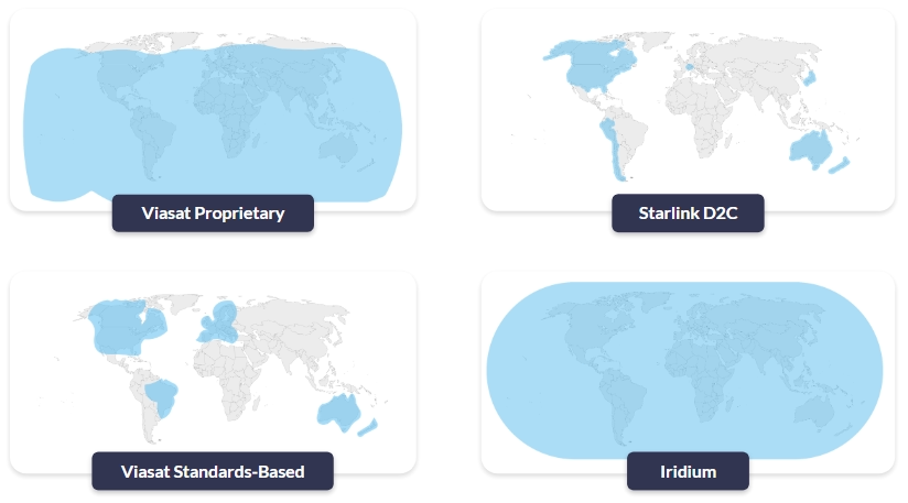
The sweet spot for satellite IoT is services in the L-band radio frequency, as these need very little power and are largely unaffected by poor weather. They’re suited to much smaller data volumes, and fit an IoT use case perfectly, for example, regular level and water quality readings from a buoy, float, or river gauge.
So, who offers L-band services? The pre-eminent Satellite Network Operators (SNOs) are Iridium, Viasat (Inmarsat) and Globalstar. Of these three, Iridium is the only one that is truly global. Viasat has great coverage but doesn’t cover the poles, and Globalstar has some big gaps over Asia, the polar regions and the oceans.
Now we have to go one level deeper (sorry!). Of these three, currently Viasat is the only network that offers both proprietary and standards-based services.
- “Proprietary” means that you have a Viasat chipset that works with Viasat satellites; you can’t use it to communicate with Iridium satellites, or vice versa.
- “Standards-based” refers to the use of cellular standards over satellite, namely NB-IoT and LTE Cat-1. As these are all built to the same standard, it should – when the services mature – be possible to switch supplier without needing to change your hardware.
Viasat’s proprietary services (IoT Nano, IoT Pro) are well established and available everywhere where Viasat’s satellites can see the Earth. Their standards-based service, NB-NTN, is in its infancy, and they’re turning on coverage where there’s sufficient demand. Currently that’s North America, parts of Europe, Brazil, Australia and New Zealand. Huge swathes of the ocean are not covered, and if your application is in South America (excluding Brazil), Africa or much of Asia, you’re also out of luck.
In short, check coverage carefully, particularly for maritime devices like offshore buoys, USVs or drifting floats, as claims often don’t live up to reality. For inland water sensing, don’t assume that “country-wide” includes your upland reservoir or remote abstraction point either.
Myth #2: More Bandwidth Solves Everything
Reality: Power, airtime and antennas still call the shots.
As mentioned earlier, the higher bandwidth services (e.g. Starlink, OneWeb) operate in Ku- and Ka-bands, and while these are great for moving large volumes of data, the trade-off is a higher power draw and larger, more complex antennas. If you’re operating a coastal station or treatment works with reliable power and solid mounting options, they may be a good fit. If you’re building a wave buoy with tiny solar panels, they simply can’t power these sorts of satellite terminals.
If you don’t have mains power, and therefore do need a power-efficient satellite terminal, L-band IoT services will best serve your needs. Viasat and Iridium have a wide range of IoT services that span from IP-based options such as Iridium Certus 100 (speeds up to 88 kbps) to message-based services like Viasat NB-NTN (optimized for ~50 bytes per message).
Even within specialist services for IoT, the more throughput or volume you need, the larger the antenna, and the greater the power draw. Message-based services can be more challenging to work with (we’ll come back to this), but they are the most efficient means of utilizing a satellite link, especially for water sensors that only need to report periodically.
The following simplified table lays out the trade-offs.
| NB-NTN | Short Burst Data (SBD) | Iridium Messaging Transport (IMT) | Certus 100 | IoT Pro (BGAN M2M) | |
|---|---|---|---|---|---|
| Operator | Viasat | Iridium | Iridium | Iridium | Viasat |
| Link Type | Message-based (NTN NB-IoT) | Message-based (proprietary) | Message-based (proprietary) | IP-based | IP-based |
| Data Volume | 50 bytes per message* | Up to 340 bytes per message | Up to 100 kB per message | 22/88 kbps | 464 kbps |
| Power Consumption | Very low | Very low | Low | Medium | Medium |
*There’s no hard protocol limit that stops you above a certain size; NB-IoT can technically carry up to around 1.6 kB of user data in a single packet. But current NTN NB-IoT services are engineered around tiny messages (tens of bytes) and tens of kilobytes per month per device. Anything bigger quickly becomes slow, power hungry, and uneconomic.
Myth #3: Standards Make It Simple
Reality: Coverage gaps and physical constraints still apply.
We’re very excited about the potential of standards-based (or NTN) satellite connectivity; once it matures, it should unlock massive IoT use cases that would be cost prohibitive for a proprietary solution. But it isn’t a lower cost version of the proprietary solutions that exist today; it’s a different class of connectivity.
NTN NB-IoT is designed to connect a large number of latency tolerant end points sending very small amounts of data, such as a grid of rainfall and runoff gauges across a catchment for flood risk modelling. It’s not designed for more than around 50 kB of data per month per device, and it’s not suited to real-time communication.

This is in contrast to cellular NB-IoT, which can move 1-2 kB per transmission, and is generally economically viable up to ~5 MB of data per month per device. That’s more than enough for frequent level and quality readings from a river, reservoir or pipeline monitoring point, but if you try to replicate that pattern over satellite, both cost and power consumption quickly become challenging.
If you’ve been working with cellular NB-IoT and enjoying the larger volumes of highly economical transmissions that terrestrial networks facilitate, you’re in for a bit of a shock when it comes to moving that data over satellite. You will need to be able to work within the data constraints of the NTN version, which is likely to need some data optimization (we’ll come back to this shortly).
Another consideration that may stand in the way of seamless transition between cellular and NTN NB-IoT is your antenna.
- Cellular NB-IoT is designed to work with small, low gain antennas – often just a simple PCB or stub antenna in a plastic box. While antenna placement requires some forethought (not inside a metal box, not under a pump skid etc.), it doesn’t need to be outdoors.
- NTN NB-IoT over GEO satellites is a different beast. Connecting to a satellite which is – in the case of Viasat NB-NTN – 35,786 km from Earth requires a higher gain antenna and clear line of sight to the satellite. The antenna needs to be on the roof, on a mast, on top of a buoy, not buried in a pit or down in a plant room.
Not dissimilarly to your cellphone trying to find a network, a poorly positioned antenna drains power and is more likely to drop data.
The bottom line is that NTN is viable and workable for a myriad of water-sensing applications; just not all of them. And while working with data constraints might take some getting used to, doing so has cost, power and battery life benefits. So here are our top tips for optimizing your data for streamlined transmissions.
Working With the Constraints: Design Patterns That Actually Work

Send Data Less Frequently
Instead of transmitting every second, trigger messages only on events or stretch your interval to every few minutes or hours, so you cut airtime and power without losing useful insight.

Send Less Data
Replace continuous raw streams with compressed or aggregated values (min/max/average/exceptions), sending only the fields your application actually needs rather than every sample.

Choose the Right Transport
Where you don’t need interactive sessions, use compact, message-based protocols instead of IP to avoid chatty handshakes and headers, reducing connection time, airtime use and power draw.

Position Your Antenna Well
If your satellite network is in geostationary orbit (e.g. Viasat) you need line of sight to the satellite; if it’s in Low Earth Orbit (e.g. Iridium, Globalstar) you need a clear view of the sky as the satellites move overhead
Most of the above is fairly self-explanatory, but it’s worth a quick dive into message-based protocols, because this is where many water monitoring applications can win back cost and battery life.
Why Message-Based Protocols Matter
Because cellular connectivity is abundant and cheap, most IoT applications use an IP connection to move data. We often liken this to a telephone call: an interactive, two way communication path which, while very widely used, has some drawbacks from an IoT perspective, particularly when operating with data constraints.
Firstly, the real time “conversation” between the sensor and your control centre is relatively hard on battery life. Secondly, the amount of overhead passed over that connection in addition to the actual data you need is considerable.
When you’re sending data into space, every byte matters.
Sending data over IP is not the most cost-effective, nor battery-conservative, means of using satellite IoT.
The alternative is a message-based solution, which we touched on earlier. NTN NB-IoT is message-based, as are Iridium SBD and IMT, and Viasat IoT Nano. Message-based connections are more like a text message: you send the message, receive an acknowledgement (note: not all services include this), and close the connection.
The message contains much less overhead, and the connection stays open only as long as is needed to transmit. This is the most economical way to use satellite IoT, both from a cost and power perspective. While it often requires a little more engineering work to format your data appropriately, it is usually worth the effort.
On the server / cloud side, platforms like Ground Control’s Cloudloop will decode the data on receipt and send it to your destination of choice, properly formatted, so there’s no need for engineering work on the cloud / server side.
Many applications can move to message-based transmission: data buoys, weather stations, reservoir level sensors, groundwater monitoring wells, water quality sondes and static flow/abstraction meters where data isn’t needed in real time.
If you do need real-time command and control, for example, remotely piloting a USV, or actively managing gates and valves in a complex hydraulic system, there are reliable services available, including Iridium Certus 100 and Viasat IoT Pro. But it’s definitely worth investigating message-based services if you can work with a few seconds’ latency and slightly less interactivity.
Choosing a Network: Matching Technology to Use Case
To bring this to life, we’ve put together this table to illustrate a few use cases.
| USV | Data Buoy | Profiling Float | Reservoir Level Station | |
|---|---|---|---|---|
| Movement | Mobile | Stationary | Free floating | Stationary |
| Location | Open ocean | Open ocean | Open ocean | Upper catchment / remote reservoir |
| Power Source | Solar | Solar | Battery | Solar |
| Data Volumes | High | Medium | Low | Low-Medium |
| Transmission Frequency | Real time to every 5 minutes | Hourly | Hourly to every 10 days | Every 5-15 minutes + event driven |
| Suggested Service | Iridium Certus 100 or Viasat IoT Pro | Iridium Messaging Transport (IMT) | Iridium Short Burst Data or (if within coverage) Viasat NB-NTN | Iridium Messaging Transport (IMT) |
| Suggested Device | RockREMOTE Mini | RockBLOCK 9704 | RockBLOCK 9603 | RockBLOCK Pro |
If the device needs a real time connection, it needs an IP-based service, but if it’s solar powered, it needs to couple that requirement with high power efficiency. Iridium Certus 100 or Viasat IoT Pro meet both requirements, and are your best options here.
If the device is running exclusively on a battery, and has very low data requirements, this is a great application for NTN NB-IoT (Viasat’s brand for this service is NB-NTN). However, you need to check coverage. If coverage is not available, Iridium’s Short Burst Data (SBD) service is a cost effective and global alternative.
If data volumes are larger, Iridium Messaging Transport (IMT) can carry up to 100 kB per message, and the modules can also be powered by a battery. In each case, there are several options for the device that houses the module, ranging from enclosed and vibration-tested devices with simplified commands (RockBLOCK Pro) to developer PCBs with a choice of internal or external antennas (RockBLOCK 9704 / 9603).
Designing the Right Data Path for Your Water Sensors
The headline story around NTN is seductive: one chipset, everywhere connectivity, cellular-like costs. For water monitoring teams under pressure to instrument more assets – more rivers, more reservoirs, more outfalls, more offshore platforms – it sounds like the silver bullet we’ve all been waiting for.
It isn’t. But it can be a powerful new tool in the box if you treat it as such.
If there’s one takeaway from this post, it’s this: everywhere IoT is not something you buy; it’s something you design.
For water sensing, that design work boils down to a handful of questions:
- Where are my sensors, really? Open ocean, estuary, upland catchment, plant room? Coverage claims matter less than the actual map.
- How is each device powered? Battery, micro-solar, or a nice fat cable from the control room?
- How quickly do I genuinely need the data? Seconds, minutes, hours?
- How much data do I actually need to move? Raw streams, or carefully chosen summaries and alarms?
Answer those honestly, and the right combination of L-band IoT, NTN, cellular and (where appropriate) broadband satcom usually reveals itself.
Need Help Getting Data Home?
If you’re looking at a new water-monitoring project, from data buoys and USVs to flood-warning networks and smart reservoirs, and you’re not sure where to start, we’re happy to help.
Ground Control has spent the last two decades getting data out of some of the world’s most awkward places. We can’t promise magic, but we can promise clear advice, realistic trade-offs, and solutions that actually work when it’s dark, cold and raining sideways.
Complete the form, or email hello@groundcontrol.com, and we’ll reply within one working day.